
|
 08 August 2012, 19:34
|
#221 | |
|
Registered User
Join Date: Mar 2004
Location: finland
Posts: 1,841
|
Quote:
|
|

|
|
08 August 2012, 19:53
|
#222 | |
|
Registered User
Join Date: Nov 2010
Location: Sweden
Posts: 528
|
Quote:
|
|
|
|
|
08 August 2012, 20:10
|
#223 |
|
Registered User
Join Date: Apr 2012
Location: Canada
Age: 44
Posts: 910
|
I am wondering whether what appears to be a Samsung Rev TA can be modded?
|
|
|
|
13 August 2012, 10:02
|
#224 |
|
Registered User
Join Date: Aug 2012
Location: RAM:
Posts: 83
|
Hi,
I have a question for owners of Sony MPF920-E E/131.  Do you have any theory where the loose spring is supposed to be?  I have a drive here without working eject mechanism. When pressing the button, the disk is lifted, but not ejected. I think the spring is supposed to be connected to the white plastic lever, but I can't figure out how. I have a drive here without working eject mechanism. When pressing the button, the disk is lifted, but not ejected. I think the spring is supposed to be connected to the white plastic lever, but I can't figure out how.I intended to mod this drive for my A4000. |
|
|
|
13 August 2012, 11:00
|
#225 |
|
Registered User
Join Date: Apr 2010
Location: Italy
Posts: 1,136
|
insert the spring on part plastic white like a tube
|
|
|
|
13 August 2012, 13:30
|
#226 |
|
Registered User
Join Date: Aug 2012
Location: Melbourne, Australia
Posts: 888
|
I stumbled across the below instructions from Kipper for the Panny JU-256:
http://www.kipper2k.com/amiga/198pchires.jpg and I had a JU-256a88p lying around and decided to give it a go (looks very similar to his model): http://dl.dropbox.com/u/71121999/Ami...2012.24.25.jpg and it works perfectly: http://dl.dropbox.com/u/71121999/Ami...2012.49.26.jpg Nice one Kipper! It doesnt work with HD disks on my 500+, but to be honest I really dont mind. |
|
|
|
14 August 2012, 08:34
|
#227 | |
|
Registered User
Join Date: Aug 2012
Location: RAM:
Posts: 83
|
Quote:

|
|
|
|
|
14 August 2012, 10:30
|
#228 | |
|
Registered User
Join Date: Apr 2010
Location: Italy
Posts: 1,136
|
Quote:
|
|
|
|
|
14 August 2012, 17:07
|
#229 | |
|
Registered User
Join Date: Aug 2012
Location: RAM:
Posts: 83
|
Quote:
|
|
|
|
|
22 August 2012, 12:23
|
#230 |
|
Posts: n/a
|
Mitsumi D359t5
Just a quick question
I need to mod a D359T5 I understand about moving the small components from Ds1 to Ds0, dch to rdy and then running a wire from DCH to pin 2 But on no photos or pages on the internet does it show if I need to cut any existing connections on the pcb (scrape a small section of the copper channel) Can anyone help? |
|
30 August 2012, 01:24
|
#231 |
|
Registered User
Join Date: Apr 2012
Location: Canada
Age: 44
Posts: 910
|
I have decided to take the risk and bought a whole bunch of Samsung SFD-321B drives, Rev. TA. They are all brand new, were pretty cheap and frankly the only ones I could find.
I am looking at the PCB and what I am seeing here is the DC and RDY resistors soldered: great, none of the other PC drives I have have those. However there is NO DS0/DS1 select resistor on this PCB. This kinda sucks since by following the usual Samsung mod I can get these drives to work as DF1: in big box Amigas, but not with the 500/600/1200. I am attaching a high res pic of the PCB below. My question is: is there any way to make the drive identify itself as DS0? Could this be selected through the flat cable (perhaps using the IBM "twisted" cable?) 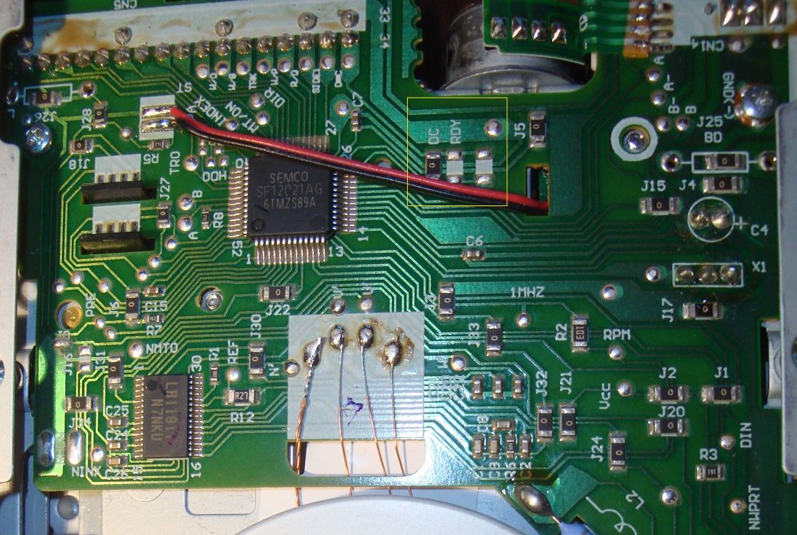
|
|
|
|
30 August 2012, 12:23
|
#232 |
|
Registered User
Join Date: Apr 2010
Location: Italy
Posts: 1,136
|
you need break the wire pin 12 and connect to pin 10 or twisted on cable
|
|
|
|
30 August 2012, 20:09
|
#233 |
|
Registered User
Join Date: Apr 2012
Location: Canada
Age: 44
Posts: 910
|
OK, thanks. This seems simpler than I thought. Basically I could cut the trace to pin 12, then jumper the trace onto pin 10 and eventually cut the original pin 10 trace, except it doesn't seem to be on the surface of the PCB, so maybe twisting the flat cable wire is an easier solution, but technically everything should work 100%. Will test and report back.
EDIT: apparently the purpose of the common twisted IBM-PC floppy drive cable is to make the drive appear as DS0 after the twist. So using one of those cables instead of regular Amiga cables should solve the problem without the need for all the trace cutting to achieve DS0. Last edited by alenppc; 30 August 2012 at 20:35. |
|
|
|
30 August 2012, 20:38
|
#234 |
|
Registered User
Join Date: Apr 2010
Location: Italy
Posts: 1,136
|
i suppose pin 10 nc, not connected, you can see that in order to save money, missing many pin odd
|
|
|
|
31 August 2012, 02:49
|
#235 |
|
Registered User
Join Date: Apr 2012
Location: Canada
Age: 44
Posts: 910
|
OK, I have had some success.
This is what I did: move the DC resistor to either the RDY pad or the empty one next to it. They appear to be identical although I have no clue why; On some drives the empty pad contains solder blobs while the RDY does not, so there is no choice but to use the other one. Either way, it seems to work. Solder the lower pad of the now empty DC resistor (covered by the red wire in the picture) spot to pin 2. Pin 10 is not connected to anything, so a connection can be made between pins 10 and 12 on PCB and Pin 12 pulled out of the connector. This makes the drive identify as DS0 with proper diskchange signal. The Amiga reads all the floppies great, no errors. However while trying to format a disk or to write: I can't. I tried formatting several floppies but it does not seem to work at all. The drive gives weird sounds (sounds like it retries every track) as it's formatting and eventually fails on cyl 79. If I attempt to reformat the same disk again, it fails immediately on cyl 0. What could be causing this? Any ideas? It might be just a bad drive, so I'll try modding another but somehow I doubt that's the reason... |
|
|
|
31 August 2012, 08:47
|
#236 | |
|
Posts: n/a
|
Quote:
|
|
|
31 August 2012, 14:54
|
#237 |
|
Registered User
Join Date: Apr 2012
Location: Canada
Age: 44
Posts: 910
|
Mat_trick: the best thing is to do is to try it out first without cutting any traces. The only potential problem I could see is that pin 2 is wired to HDselect signal on the IBM-PC interface, so I could see that interfering (someone correct me if I am wrong).
I have tried cutting that trace on my drive to see whether this is what causes the write malfunction, but it made no difference. |
|
|
|
31 August 2012, 15:03
|
#238 | |
|
Registered User
Join Date: Sep 2006
Location: Thunder Bay, Canada
Posts: 4,323
|
Quote:
there is quite a selection... http://www.pitsch.de/stuff/amiga/floppy.htm |
|
|
|
|
01 September 2012, 02:21
|
#239 |
|
Registered User
Join Date: Apr 2012
Location: Canada
Age: 44
Posts: 910
|
Ok, I have modded a second drive, and I can confirm that the mod is more or less complete.
I still can't format my old disks, but I think I have discovered the reason for this: these drives are incredibly poor quality. It would probably work with brand new disks, but my disks are 20 years old. This drive is incredibly picky about what it works with. The original floppies work fine, even non-dos ones, as for Amiga written disks, it's very hit and miss. It won't read the usual HD disks formatted as DD (even with the hole covered), most of my old DD disks work, but only if they are good quality, not the cheapo ones. The drive build feels VERY flimsy, the solder joints are really crappy, so I think its construction is generally very very poor. In any case, here's the drive PCB with modifications: it behaves as a regular Amiga drive, works as DS0 and works with OK with the Ready signal. If I manage to find some new DD floppies I will try formatting them to see what comes out. You will notice that this particular unit has no solder joints on the RDY pad (unlike the one I photographed above), so I joined the one next to it and this did the trick. 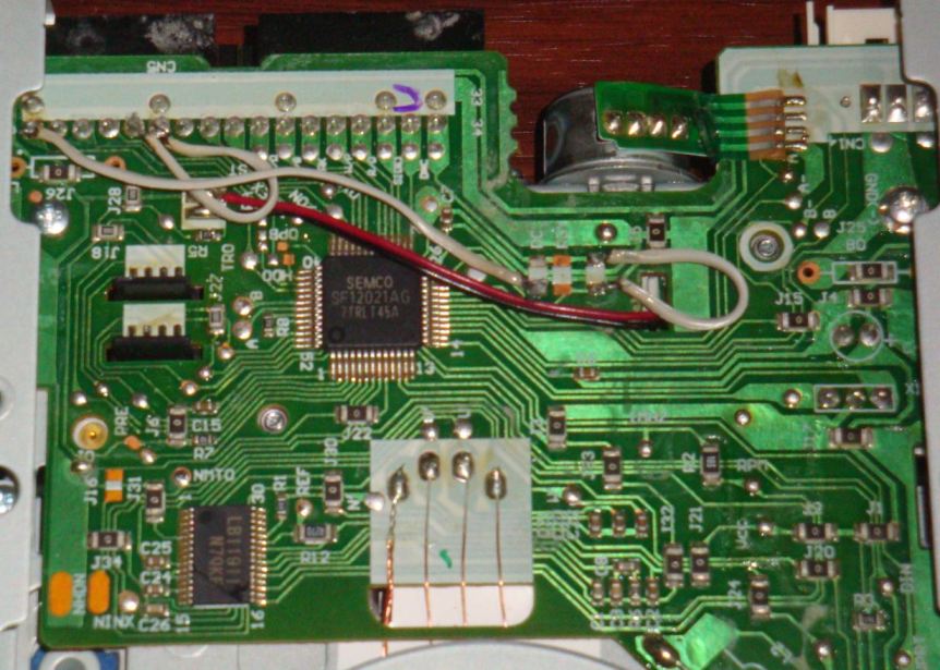 So here you go, DC to pin 2, RDY joined, Pins 10 and 12 connected, pin 12 pulled out of the connector (be careful not to touch the metal shield). 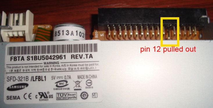 Conversely, the original Chinon drives, modded PC Chinon FZ-354s, Commodore A1010s and so on pretty much read everything. That's the difference in quality building. |
|
|
|
04 September 2012, 15:29
|
#240 |
|
Posts: n/a
|
Yeah I guessed I could try it without cutting any channels, I just don't want to damage the drive.
I looked at the link and apart from it being in German It looks like I don't need to cut a channel. Everywhere I looked states what mods to do on this drive but no one mentions cutting an existing channel. If pin two is already conected to the processor chip, surely I need to cut it to prevent malfunction ???? |
| Currently Active Users Viewing This Thread: 1 (0 members and 1 guests) | |
| Thread Tools | |
 Similar Threads
|
||||
| Thread | Thread Starter | Forum | Replies | Last Post |
| Amiga 5.25-inch floppy disks and drives | mips | support.Hardware | 25 | 28 October 2023 14:54 |
| Copying Amiga disks using Floppy drives on a PC. | hamster | support.Hardware | 22 | 01 September 2020 10:46 |
| List of Amiga compatible PC floppy drives | Olecranon | support.Hardware | 12 | 05 October 2011 17:38 |
| Amiga floppy drives | cinemawareman | Amiga scene | 5 | 17 March 2011 15:40 |
| replacing amiga floppy drives with hard drives | Gordon | support.Hardware | 2 | 06 March 2007 00:44 |
|
|


