Yesterday night I noticed I had a Panasonic JU-257A606P sitting on my shelf..
I remembered that there was an article about that on Aminet regarding how to use it with the Amiga. So, let's download that and see.
It seems the article deals with a very old revision of the A606P, one that I've never seen in the wild.
Naturally the component positions are totally different in these that I've seen.
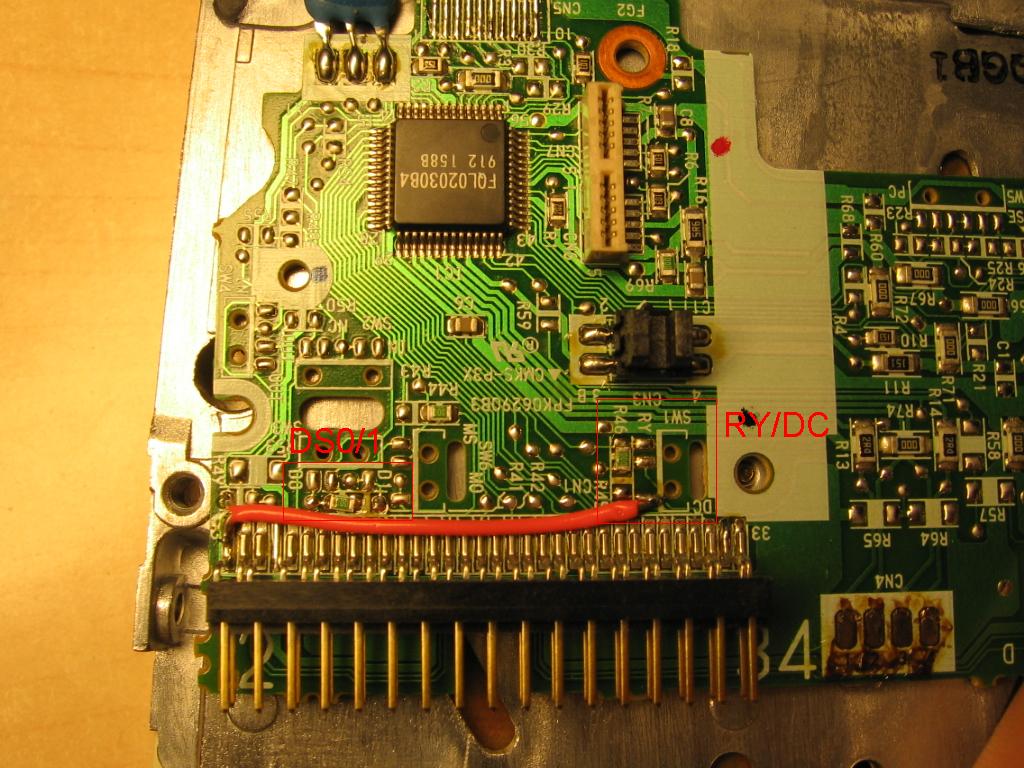
Oh well, the document told me enough. Get _RDY to pin 34 and _DC to pin 2, make the drive answer to DS0 instead of DS1.
So, judging by the grainy shot, I did the same as the author. I found the place where DC/RY switch is supposed to be, moved the SMD jumper from the DC position to RY and soldered a small wire from the DC pad to pin 2 on the data connector. Then I found the DS 0/1 switch position and moved the jumper block from DS1 to DS0. Slap the bugger back together and plug it into the
A1700 that is conveniently without a top cover.
My trembling hands insert Sanity's Arte, a demo that is known to require the ready signal.
It works! Yay.
In case you didn't understand my written instructions, here's an illustration on how the SMD jumpers and wire are supposed to go:
So how to tell which one to get?

Notice the flexi cable that goes to the stepper motor. It has to go to the right for the above illustration to apply. This is if you feel that you cannot work it out on your own for a different PCB.
So what do I do today? Go down to the recycling center (it's open every day of the week :-D) and buy 10 A606Ps, taking care to get the same PCB revision as the one I had success with. I also purchased two that had different PCBs, one with the flexi cable going left and one that has a connector for the stepper motor.
The one with the flexi going left worked. Naturally the switch positions are different, but you can hopefully work it out on your own.
The one with the connector for the stepper cable didn't work, even though I tried to measure all the "switches" and verified that they are in the same position. Not a big deal, I can handle the financial loss. Perhaps it was broken to begin with or perhaps it just isn't Amiga friendly. :-)
I think that the best success will be on drives that have only two positions for the DC/RY switch. The one that failed had four positions there.
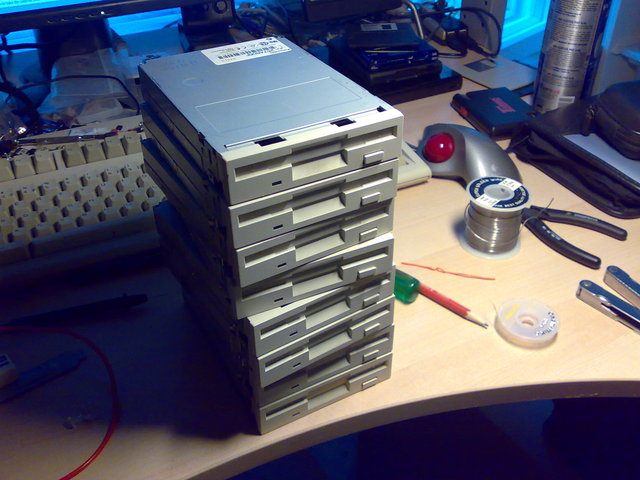
Eight drives, ready to be plugged into an Amiga. Anyone want to buy some? I'm probably going to ebay a few, but I'm also open for offers directly. These are great for aftermarket towers. (DS1 versions available per request)
I got rather quick at this.. 5mins per drive after a bit of practice. :-D
If you're wondering where three of them went, one is in my broken drives pile and two are in the A2000T.
These also work nicely in a dual drive configuration for a big box Amiga. If you want it to be DF1, don't swap the DS jumper. Have a cable with only wires 4-6 twisted. DF0 is DS0 and DF1 is DS1. Remember to close the "DF1 present" jumper on your motherboard.
Oh, please recommend other software that needs the ready signal! I'd like to test them more thoroughly. I have verified that Arte will not boot past the boot block without a ready signal.