 |
|
|
#1 |
|
Registered User
Join Date: Dec 2002
Location: sweden
Age: 46
Posts: 430
|
a1200 DF0/DF1 switch - help!
Hi! I am planning to hook up an hxc floppy emulator to the circuits of a slaughtered extra drive.
All fine so far, the drive is connected and powers up. But i want to make it switchable to DF0 by hardware as i want to be able to boot stuff that is hardcoded for DF0:... I understand that this is possible by connecting a switch to SEL0 and SEL1. You also need to cut two traces on the mobo. But I am unsure exactly which pin is sel0 and sel1 and what traces to cut. Could some kind soul please mark these out on this image? http://bboah.claunia.com/a1200mb_rev1d4.jpg |
|
|
|
|
#2 |
|
-
Join Date: Jul 2003
Location: Helsinki / Finland
Age: 43
Posts: 9,861
|
I wouldn't cut anything, I'd bend out the select pins instead.. Then you can just connect wires to them. If you ever want to reverse the mod, then just gently bend the pins back and solder them back down.
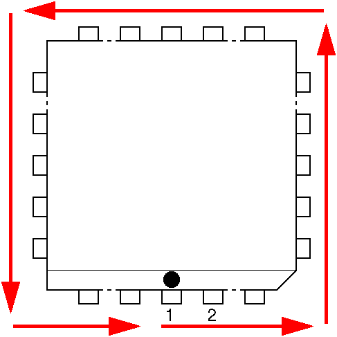
Pin 1 is where the dimple is on the middle of one of the sides of the chip. It is also marked on the silkscreen next to the dimple. Then you start counting anti-clockwise.  Pinout here: http://www.amiga-stuff.com/hardware/8520.html Don't try to solder the wires under the chip, solder them to the underside of the motherboard at the external and internal floppy ports instead. If you're clever with your wiring, you can do this with only four wires and a DPDT switch. |
|
|
|
|
#3 |
|
Registered User
Join Date: Dec 2002
Location: sweden
Age: 46
Posts: 430
|
thanks for the input. those legs are so damn small, how would you do if you wanted to bend them out? what tools would you use?
|
|
|
|
|
#4 |
|
-
Join Date: Jul 2003
Location: Helsinki / Finland
Age: 43
Posts: 9,861
|
I would use a soldering iron + a small hobby knife. Wedge the knife tip under the leg, then heat it up with the iron. Once the solder melts, you bend up the leg.
There's a big possibility of ruining your cia chip or motherboard here though, I recommend practicing on some piece of broken consumer electronics that has a PLCC chip on it, such as an old PCI or AGP graphics card, those usually have the BIOS in a PLCC package. |
|
|
|
|
#5 |
|
Registered User
Join Date: Dec 2002
Location: sweden
Age: 46
Posts: 430
|
I think i'll try to avoid bending legs and cut a trace or two on the mobo instead.
I bought the needed DPDT switches today.  Could anyone give advice on where to cut and where to connect the wires? |
|
|
|
|
#6 |
|
Registered User
Join Date: Dec 2002
Location: sweden
Age: 46
Posts: 430
|
bump! has anyone ever done this mod on an a1200!?
|
|
|
|
|
#7 |
|
-
Join Date: Jul 2003
Location: Helsinki / Finland
Age: 43
Posts: 9,861
|
Probably not, but the instructions are all there.
I'd probably cut DS0 right next to the internal floppy header and DS1 next to the external floppy connector. I hate cutting traces unless I have to, that's why I recommended the bend up method instead. |
|
|
|
|
#8 |
|
Registered User
Join Date: May 2001
Location: ?
Posts: 19,645
|
I am interested in doing this gotek<>floppy switch, but I had not read until this thread that you need to lift a pin or cut a trace on teh computer. I thought you just had to redirect the SEL signal.
Also I read that if I use a DPST switch (do I need DT? why?), I can also do it so I can keep both drives operating, instead of switching from one to the other. Can this info be clarified for this dummy so I don't go doing the wrong thing? I intend to do this for both an A500 and an A600. |
|
|
|
|
#9 |
|
Registered User
Join Date: Jan 2017
Location: Australia
Posts: 84
|
do not touch the chip or bend legs, you will damage the chip beyond repair.
just cut the tracks **carefully** then if you want to reverse it simply scratch the green mask off the trace and join it with a small piece of wire taken from a multi-strand piece of wire. in other words a very very tiny piece of wire about 0.15mm in diameter. add flux and solder then heat and it will stick. a good large magnifier and tweezers also helps. as for the double pole, it is needed to switch both if you want both working. the info is here.... http://eab.abime.net/showthread.php?t=39776 the principle is exactly the same as the A500, the only difference is the chip is a different shape and surface mounted. |
|
|
| Currently Active Users Viewing This Thread: 1 (0 members and 1 guests) | |
| Thread Tools | |
 Similar Threads
|
||||
| Thread | Thread Starter | Forum | Replies | Last Post |
| Swapping DF0 and DF1 on A600? | CrazyIcecap | support.Hardware | 41 | 07 October 2016 14:20 |
| Df0: Df1: | Muerto | support.WinUAE | 3 | 19 May 2007 00:46 |
| DF0 + DF1 connection? | Fingerlickin_B | support.Hardware | 2 | 14 March 2007 08:53 |
| Renaming DF0: to DF1: at boot | Rochabian | support.Hardware | 10 | 29 January 2007 16:21 |
| DF1: to DF0: | Carlos Ace | support.Games | 4 | 27 May 2002 00:20 |
|
|