
|
 16 November 2017, 03:26
|
#1 |
|
Ruler of the Universe
Join Date: Mar 2010
Location: Lanzarote/Spain
Posts: 6,185
 |
Making a new C=64 PSU
Hi:
I want to make a new power supply for my old Commodore 64 breadbin before it's too late. The Commodore 64 requires a power supply that provides both 9V AC and 5V DC. I'm thinking in buying this 9v AC adaptor: 1A/1000MA 9V 9VA AC/AC OUTPUT MAINS POWER ADAPTOR/SUPPLY/CHARGER/TRANSFORMER And this 5volts DC one: 1 St. Netzteil: Impuls; 15W; 120÷370VDC; 85÷264VAC; Ausgänge:1; 5VDC; 3A First I want to know if they will be ok to make a new power supply and in second place I would appreciate if someone could post some picture about how to connect it, where to add some fuses, which, etc. Please remember that any explanation has to be easy to understand for everybody as I think that any help here will be useful for others. Last edited by Retrofan; 22 February 2018 at 01:09. |

|
|
16 November 2017, 04:49
|
#2 |
|
Registered User
Join Date: Aug 2004
Location: 19 Jump Street
Posts: 238
|
<offtopic>
This is a little off-topic since you want to build a PSU, but if you or anyone else wants to buy a newly built PSU, Ray Carlsen builds and sells them from his website at http://personalpages.tds.net/~rcarlsen/custom%20ps.html I've ordered both C64 and Amiga ones in the past. Both were high quality and were completed within days. </offtopic> |
|
|
|
17 November 2017, 00:25
|
#3 |
|
Registered User
Join Date: Apr 2016
Location: Greensboro, NC USA
Age: 32
Posts: 116
|
Those two adapters sound fine to me. I have no soldering experience and built my own a few years back the same way. I didn't add any fuses myself, since the modern wallwarts "shouldn't" malfunction any time soon. If you make one without a fuse, you can always pick up the kits folks at lemon64 (and I assume amibay as well) make, for like $15 or $20 if I remember correctly.
I will tell you that this conversation occurs a minimum of once a week on lemon64's message boards, and the documentation over there is very very good (they have a lot of experts, who love to share knowledge!). I'd recommend just spending half an hour using the search function over there. |
|
|
|
17 November 2017, 13:50
|
#4 |
|
Registered User
Join Date: Apr 2011
Location: Stoke on Trent
Age: 52
Posts: 63
|
There's a good project here:
[ Show youtube player ] Links to shematics and write up in the description. |
|
|
|
23 November 2017, 16:32
|
#5 | |
|
Ruler of the Universe
Join Date: Mar 2010
Location: Lanzarote/Spain
Posts: 6,185
|
This is what I've done:
        I haven't tried it yet and I want to add the final touch. I will check the pinout and the cables first. Edit: I see that in my PSU, the white cable is pin 5 and it has to be +5V, but I've heard about pin 5 brown. My brown cable is pin 6 instead, for 9Vac: Pin 5 white 5V+ Pin 2 green 0V Pin 6 brown 9V~ Pin 7 yellow 9V~ This is the best image (female socket), taken from my book:  Let's hope that I won't fry anything. Edit: I've received a tip and I will use it: Quote:
Last edited by Retrofan; 25 February 2018 at 02:08. |
|
|
|
|
25 November 2017, 21:51
|
#6 |
|
Ruler of the Universe
Join Date: Mar 2010
Location: Lanzarote/Spain
Posts: 6,185
|
Just to comment also about this new Psu that I've bought (I've got four C64's). I think it has a good price and it also has a cable long enough:
https://www.ebay.es/itm/New-Commodor...YAAOSwYwJaDXiD Edit: I've checked the continuity of the cables and it is ok with the pins now, but I can't check the volts of each line because my multimeter has a blown fuse and I'll have to wait for a replacement. In any case I've switched it on while connecting it to one of those new C64's power savers and the led turns on ok. I won't try it yet with the C64. Last edited by Retrofan; 05 December 2017 at 00:45. |
|
|
|
08 December 2017, 16:35
|
#7 |
|
Ruler of the Universe
Join Date: Mar 2010
Location: Lanzarote/Spain
Posts: 6,185
|
The power saver I bought at Ebay for the PSU was needing a box, so I've bought an empty C64 cartridge and I've adapted it using the dremel:

Last edited by Retrofan; 25 February 2018 at 00:53. |
|
|
|
16 December 2017, 23:51
|
#8 | |
|
Ruler of the Universe
Join Date: Mar 2010
Location: Lanzarote/Spain
Posts: 6,185
|
I've finally added another fuse for 5V and a Zener diode after it.
And I've added my final touch: A voltmeter/ammeter with LED display. And as Ray Carlsen says: Quote:
     
Last edited by Retrofan; 25 February 2018 at 02:10. |
|
|
|
|
17 December 2017, 00:46
|
#9 | |
|
CaptainM68K-SPS France
Join Date: Dec 2004
Location: Melun nearby Paris/France
Age: 46
Posts: 10,412
 |
Quote:
|
|
|
|
|
17 December 2017, 02:46
|
#10 | |
|
Ruler of the Universe
Join Date: Mar 2010
Location: Lanzarote/Spain
Posts: 6,185
|
Well, that's you, LOL . I prefer mine instead. Original cover, newer and much improved components from the original, fuses, Zener diode and a LED display for volts and current to give a modern look and at the same time some important information while keeping the original retro look
 . .Edit: The diode wasn't working right so it's out of the project now (well, I've added it to the mobo instead http://eab.abime.net/showpost.php?p=1221362&postcount=7) . I asked Ray Carlsen and he told me: Quote:
And... another thing: My working original C64 PSU suddenly died. At least it didn't fry anything, but I will have to use it now to make another PSU just like the one I've made and shown in this thread. Edit: About this psu, it was giving problems with the Robocop II cartridge, showing bad graphics after a few moments playing. So I tried with shorten cables and the Robocop cartridge was having the same problem, so then this afternoon I've dismounted another psu that works right with that game (a psu that I bought at Ebay) and I've installed it instead of the ones I was using, inside the C64 psu case. And... the Robocop cartridge was showing the problem again....  So what I've done is to desolder the 5v cable that the voltmeter display board uses that I had connected to about 6 cms of the cable that comes from the 5volt DC psu and I've connected it directly to the point where it delivers 5v in the board. I just thought/think that connecting it as it was, then it was drawing more power from the 5v cable that goes to the C= ... And it works now. Robocop works without any problem. BTW I see that using the Ultimate II cartridge the current changes a lot. I suposse that's normal. [ Show youtube player ] And I've changed the psu din connector using a Rean with golden pins: EDIT: ... BLABLABLA... ALL of the images just disappeared from the site, so I will post some of them here now. Yep, you can call me "The man with the Caliper view" or something : 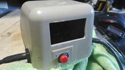 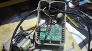  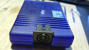 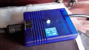 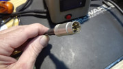  But I changed some things afterwards, just as commented. Last edited by Retrofan; 23 May 2018 at 02:58. |
|
|
|
| Currently Active Users Viewing This Thread: 1 (0 members and 1 guests) | |
| Thread Tools | |
 Similar Threads
|
||||
| Thread | Thread Starter | Forum | Replies | Last Post |
| Amiga 500 PSU ref P.312503-03 singapore (Heavy PSU) | dlfrsilver | support.Hardware | 15 | 07 October 2020 17:28 |
| A4000 PSU -> Mini-ATX PSU mod | keropi | Hardware mods | 53 | 09 December 2019 03:52 |
| Amiga 500 PSU ref P.312503 WEST-GERMANY (Light PSU) | dlfrsilver | support.Hardware | 0 | 18 November 2014 00:54 |
| Making the A4000 PSU less noisy | 8bitbubsy | support.Hardware | 7 | 15 October 2011 17:21 |
| Making a CD | Champions_2002 | request.Old Rare Games | 2 | 11 April 2003 04:23 |
|
|


