
|
 15 June 2012, 13:38
|
#1 |
|
Ruler of the Universe
Join Date: Mar 2010
Location: Lanzarote/Spain
Posts: 6,185
 |
A1200 Wrong Colors
Hi:
This is my "new" 1D1 mobo that I recently fixed repairing a problem with the joystick. It shows too much blue, so the icons are like violet.  This is using Amigakit's scart, that works perfect with the other Amigas. What can it be? Caps? I cleaned the pins of the connector and I thought it was ok, but as you can see it isn't. Last edited by Retrofan; 15 June 2012 at 20:20. |

|
|
15 June 2012, 17:07
|
#2 |
|
Banned

Join Date: Aug 2011
Location: Saturn
Age: 52
Posts: 279
|
lack of green
check around the sony chip for small ceramic caps and resistors in bad state |
|
|
|
15 June 2012, 19:49
|
#3 | |
|
Ruler of the Universe
Join Date: Mar 2010
Location: Lanzarote/Spain
Posts: 6,185
|
Quote:
Nice, but no idea which is the sony chip: 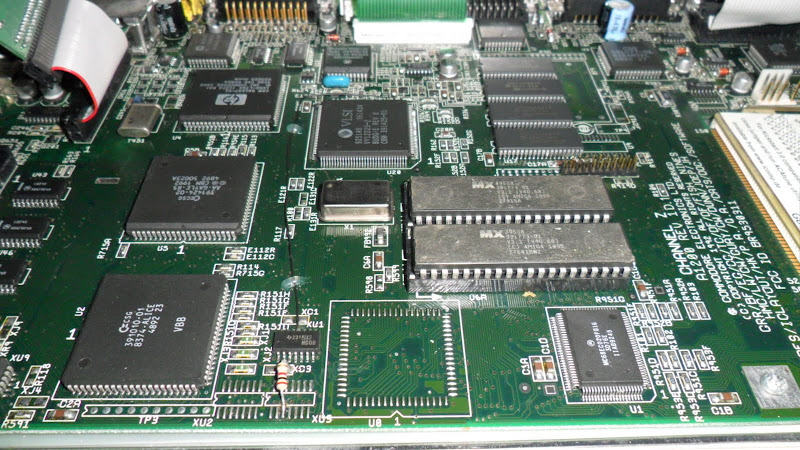 Or here: http://amiga.resource.cx/photos/phot...res=hi&lang=en Well, I don't have any cable soldered like in that photo in the chip ADV10 Last edited by Retrofan; 15 June 2012 at 19:59. |
|
|
|
|
15 June 2012, 20:03
|
#4 |
|
Registered User
Join Date: May 2006
Location: Kilmacolm
Age: 45
Posts: 632
|
Sony chip is U12 to the left of IDE connector.
Are you using RGB->SCART cable? I had the idea that this chip was not related to RGB output, only RF and composite? |
|
|
|
15 June 2012, 20:10
|
#5 |
|
Banned
Join Date: Aug 2011
Location: Saturn
Age: 52
Posts: 279
|
the sony cxa1145 near the ide connector (24 pins)
RGB lines pass through there and are amplified by the chip,and they end up in the 23 pin video port |
|
|
|
15 June 2012, 20:16
|
#6 |
|
Ruler of the Universe
Join Date: Mar 2010
Location: Lanzarote/Spain
Posts: 6,185
|
Yes, I had the Ide cable over it, so I didn't see it.
But I don't see anything wrong:  I can do any amplified photo, with an usb microscope that you ask me. |
|
|
|
15 June 2012, 20:19
|
#7 | |
|
Banned
Join Date: Aug 2011
Location: Saturn
Age: 52
Posts: 279
|
Quote:
the chip also offer SVHS if you do a little circuit |
|
|
|
|
15 June 2012, 20:23
|
#8 |
|
Registered User
Join Date: Apr 2010
Location: Italy
Posts: 1,136
|
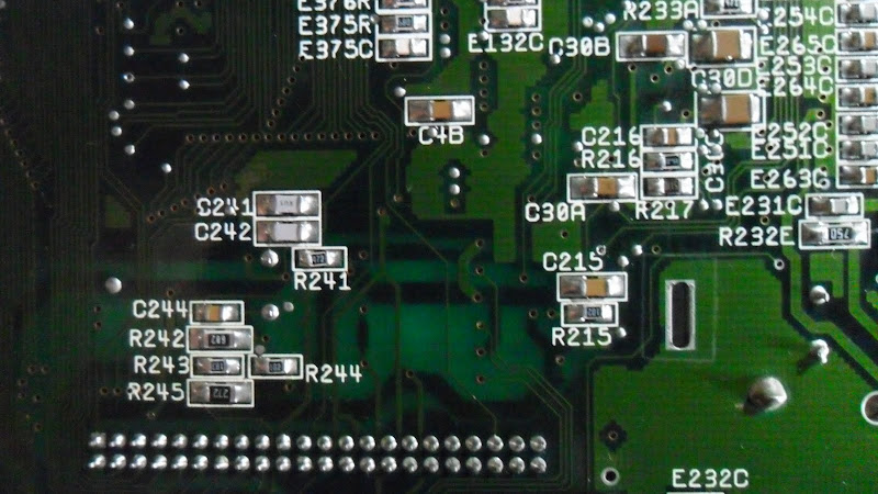
i repaired one with same defect, remove C216 10uF near ide port and verify continuity of 3 wire go to under cxa
|
|
|
|
15 June 2012, 20:49
|
#9 | |
|
Ruler of the Universe
Join Date: Mar 2010
Location: Lanzarote/Spain
Posts: 6,185
|
Quote:
 So C216 out? Or do I replace it with another? |
|
|
|
|
15 June 2012, 20:54
|
#10 |
|
Registered User
Join Date: Apr 2010
Location: Italy
Posts: 1,136
|
sorry, c219 ? don't remember, look chip cxa, you can look 3 wire at the right from transistor.
sorry find a photo and modify for more info |
|
|
|
15 June 2012, 21:05
|
#11 |
|
Ruler of the Universe
Join Date: Mar 2010
Location: Lanzarote/Spain
Posts: 6,185
|
It seems cap 21(4)¿?

|
|
|
|
15 June 2012, 21:18
|
#12 | |
|
Registered User
Join Date: Apr 2010
Location: Italy
Posts: 1,136
|
sorry i am mistake with a600, verify color form rf or composite, test R232a, R232b and R232c 24.9ohm
Quote:
Last edited by prowler; 15 June 2012 at 22:14. Reason: Back-to-back posts merged. |
|
|
|
|
15 June 2012, 22:55
|
#13 |
|
Ruler of the Universe
Join Date: Mar 2010
Location: Lanzarote/Spain
Posts: 6,185
|
Before I'll start desoldering and changing them (I can't check them) I've got a doubt. When I got the mobo I was trying to repair a joystick problem, and apart of a chip I changed, I found another thing in the mobo, that I repaired. Now I'm not sure if the Amiga had this colors before.
The smd I repaired was R370C. Has it something to be with the colors? I mean, perhaps it doesn't need that piece.   Edit: Well, here it has it: http://amiga.resource.cx/photos/phot...res=hi&lang=en Last edited by Retrofan; 15 June 2012 at 23:11. |
|
|
|
15 June 2012, 23:51
|
#14 |
|
Registered User
Join Date: Feb 2012
Location: Tayside
Posts: 181
|
I had a similar problem in the mid 90s with my 1200 but the problem was with the 'grey' having a slight 'pink' tint to it. I sent to a repair place (advertised in AF) and they told me it was a 'dry solder' problem.
I believe the problem happen, after my 1084 was knocked over, and the 1200 went 'flying' and was suspended in mid air (via the monitor lead). probably not much help, but you never know. |
|
|
|
16 June 2012, 02:05
|
#15 |
|
Ruler of the Universe
Join Date: Mar 2010
Location: Lanzarote/Spain
Posts: 6,185
|
I've checked searching for dry joints, resoldering all, broken traces, nothing.
I desoldered my replaced smd and nothing. Now soldered again. Can't it be just the Sony chip? I could try to solder another from a donnor. If you don't say no I'll try tomorrow. I've tried with the RF but coudn't watch it (perhaps had to change something of my Tv, dunno). With the Composite I have first this:  And this at the end: 
Last edited by Retrofan; 24 July 2012 at 00:05. |
|
|
|
16 June 2012, 10:41
|
#16 |
|
Ruler of the Universe
Join Date: Mar 2010
Location: Lanzarote/Spain
Posts: 6,185
|
I've changed the Sony chip with a donnor, but the result is exactly the same; not better, not worse.
Perhaps I can't fix it. Last edited by Retrofan; 18 June 2012 at 21:13. |
|
|
|
16 June 2012, 11:11
|
#17 |
|
Registered User
Join Date: May 2006
Location: Kilmacolm
Age: 45
Posts: 632
|
Hi, your pics of the composite output look to have an opposite colour problem. ie. green is back but now red is missing.
Maybe a trick of the light but maybe a clue? At least you have probably eliminated the sony chip as the cause. Also, I don't have A1200 schematics so I don't know what R370C is for. But it looks from the photo like you may have a solder bridge between the left side of that resistor and the via just below it. Maybe it is meant to connect there? |
|
|
|
16 June 2012, 12:29
|
#18 |
|
Ruler of the Universe
Join Date: Mar 2010
Location: Lanzarote/Spain
Posts: 6,185
|
No, R370C is at the other side of the board, far away, and I don't think it can be related. And there's no trick of the light, it's like that, yes rare to me too.
I'll try to change R232a, R232b and R232c as cpiac said. Edit: No, I can't. My Amiga for spares hasn't them. I'm now writing to Amigakit to see if they can fix it. Last edited by Retrofan; 18 June 2012 at 22:48. |
|
|
|
17 June 2012, 01:05
|
#19 |
|
Zone Friend
Join Date: Feb 2006
Location: Hertfordshire
Posts: 688
|
Just may be worth using the Anemos trick?..
I cannot locate the exact thread at the moment, but I had a board that was showing as pink and this mod worked with the LED alone. No harm in trying. |
|
|
|
17 June 2012, 02:06
|
#20 | |
|
PSPUAE DEV
Join Date: Nov 2006
Location: Wales / UK
Age: 45
Posts: 5,999
 |
Quote:
 . .Dont really notice, aslong as I can play games on it, I dont worry. @Retrofan If its wrong on both rgb and compsite, then it could be related to bt101 U30. Or a component linked to sony chip and U30. |
|
|
|
| Currently Active Users Viewing This Thread: 1 (0 members and 1 guests) | |
| Thread Tools | |
 Similar Threads
|
||||
| Thread | Thread Starter | Forum | Replies | Last Post |
| Virtual Karting wrong colors.... (whdload version) | keropi | support.Games | 62 | 01 July 2014 14:14 |
| A600 wrong colors | fc.studio | support.Hardware | 46 | 20 July 2012 00:23 |
| What's wrong with this A1200 motherboard? | duga | Hardware pics | 48 | 25 January 2011 18:41 |
| 8bit rtg fullscreen wrong colors | thomas | support.WinUAE | 12 | 28 July 2010 20:29 |
| HD on A1200 reporting wrong size | zeropolis79 | support.Hardware | 5 | 26 October 2009 06:00 |
|
|


