
|
 08 April 2018, 08:37
|
#1 |
|
Registered User
Join Date: May 2008
Location: Mason, Ohio / USA
Age: 48
Posts: 391
|
CD32 mouse troubles
Hiya folks
Have some mousing troubles with my CD32. Both mouse buttons work as does the up and down direction. However the mouse won't move left to right. Good working mouse. Thinking it was capacitors, I have completely recapped the board with all new SMD caps (it needed this done anyways). Still won't move left to right. My next guess is the 74LS166A shift register chip, however I am not sure. So, before I start pulling and replacing more parts, thought I would check with you guys. Thanks! todd Last edited by thgill; 08 April 2018 at 09:31. |

|
|
08 April 2018, 10:07
|
#2 |
|
WinUAE developer
Join Date: Aug 2001
Location: Hämeenlinna/Finland
Age: 49
Posts: 26,504
|
It is most likely faulty U34 (74LS166) if other joystick port's directions work normally and all connections between mouse port and U34 are fine.
|

|
|
08 April 2018, 14:22
|
#3 |
|
Registered User
Join Date: Jun 2013
Location: Australia
Posts: 685
|
Probably more likely the shift register, but the 4.7k resistor pack R370, that is holding all of the pins high is worth checking first (and the PCB traces to and from it).
|
|
|
|
03 June 2018, 08:40
|
#4 |
|
Registered User
Join Date: May 2008
Location: Mason, Ohio / USA
Age: 48
Posts: 391
|
Hey guys, I finally had some time to work on this tonight.
I replaced U34 (the LS166 shift register). Exact same results. Mouse mouse up and down, but not left to right. I tested with an original Amiga 500 mouse and a Cocolino+PS/2 mouse combo. Both exhibit the same behavior. Both mouse buttons ok and up and down movement fine. Just no left and right. So it seems something is screwing up the X axis. I tested for 5v on pin 7 of the mouse port. 5v ok. I also tested the resistors in the R370 resistor pack on the bottom of the pcb. Everything looks good. Also buzzed from pins 1-4 to the resistor pack and it was fine. Measured R352, R379 and R371. All up to spec. I buzzed from the mouse port (pins 5 and 9) back to Paula (U3) pins 35 and 36. Continuity was fine. Though I believe those lines are used for the mouse buttons? Have I missed anything? One odd thing I found was when buzzing Pin 2 of the mouse port, I couldn't find it connected to anything. According to the CD32 schematic, it's suppose to be connected to pin 4 of U34. However I don't get continuity there and I don't see a trace on the top or the bottom of the board going to anywhere at all for that pin. I suppose that could be on an inner layer (if this is a multilayer pcb), however the joystick port pin 2 clearly has a trace running from it on the bottom of the board...so I found it odd the mouse port wouldn't as well. Edit: I found the trace and I think I found the fault. It appears component E356 is bad. What is that exactly? some type of fuse? I get no continuity when buzzing both sides of it. Last edited by thgill; 03 June 2018 at 08:49. |
|
|
|
03 June 2018, 10:18
|
#5 |
|
Registered User
Join Date: Jun 2013
Location: Australia
Posts: 685
|
discontinuity for pin 2 would have the exact effect you describe. You’d loose horizontal mouse movement, and also the down direction if a joystick was in it.
It depends what part you think E356 is, because E356 is a transient protection circuit formed with two components, a ferrite bead, and a capacitor. The ferrite bead should measure dead short, and could be replaced with a wire link. The capacitor should not measure short, and shorting it would break something. The ferrite bead is a very dark shade of grey with no markings. |
|
|
|
03 June 2018, 16:50
|
#6 | |
|
Registered User
Join Date: May 2008
Location: Mason, Ohio / USA
Age: 48
Posts: 391
|
Quote:
Ahhh, I meant to attach a picture with my post. This is the part of E356 that I think is bad: 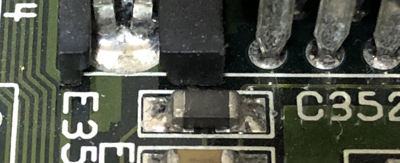 That dark grey component I believe is the ferrite bead as right below it (and partially out of frame) is the capacitor portion of e356 (which also seems to be ok). |
|
|
|
|
03 June 2018, 18:17
|
#7 |
|
Registered User
Join Date: Jun 2013
Location: Australia
Posts: 685
|
Yes, if it doesn’t measure a fraction of an Ohm resistance it’s bad.
It should be a DC short circuit, and buzz the continuity test with a meter. When that’s a thru hole component, it’s literally a piece of wire with a ferrite bead around it. You could accidentally drop a blob of solder across it. There’s nowhere else on the board to steal one from except for other ports. |
|
|
|
03 June 2018, 18:22
|
#8 |
|
Registered User
Join Date: Jun 2013
Location: Australia
Posts: 685
|
I would leave the old one there rather than removing it and linking the footprint with solder
because it looks like there’s another trace between that. I don’t think it great to blob solder straight over that mask on top of that trace. |
|
|
|
03 June 2018, 18:26
|
#9 |
|
Registered User
Join Date: Jun 2013
Location: Australia
Posts: 685
|
Hang on, don’t do that, it doesn’t work.
Having technical difficulties. Please bear with me 
|
|
|
|
03 June 2018, 18:33
|
#10 |
|
Registered User
Join Date: Jun 2013
Location: Australia
Posts: 685
|
It’s a bit risky just trying to jump with solder, but stripped mod wire is doable.
But yuk. Maybe a 0 or 1 Ohm resistor would be better. This is all assuming you’re not going to just buy a ferrite bead. |
|
|
|
03 June 2018, 18:40
|
#11 |
|
Registered User
Join Date: May 2008
Location: Mason, Ohio / USA
Age: 48
Posts: 391
|
Thanks for all your help! I’ll probably just remove the dead bead and do a wire link since I don’t have any 0 ohm resistors on hand. Then next time I place an order with Mouser or digikey I’ll order a proper replacement.
|
|
|
| Currently Active Users Viewing This Thread: 1 (0 members and 1 guests) | |
| Thread Tools | |
 Similar Threads
|
||||
| Thread | Thread Starter | Forum | Replies | Last Post |
| Jerky Mouse movement on AMIGA CD32 - normal ? | Nibbler | support.Hardware | 29 | 02 January 2016 21:38 |
| CD32 troubles streaming data | dirk_the_daring | support.Hardware | 6 | 15 October 2014 21:32 |
| cd32 newbie. mouse, keyboard, floppy games? | butfluffy | support.Hardware | 12 | 15 January 2014 17:05 |
| mouse icon pointer problem cd32 toolkit | amigapd | support.Other | 8 | 07 February 2011 09:00 |
| re cd32 keyboard and mouse conversion | calibra | support.Hardware | 3 | 19 October 2008 04:12 |
|
|


