
|
 17 February 2010, 05:30
|
#1 |
|
Brosol
Join Date: Jan 2010
Location: Vancouver, BC, Canada
Posts: 85
|
A3000 boots black screen after A3640 test install
I tried to test install a untested or possibly non-working A3640 in my A3000 (18mb RAM, KS 3.1, Agnus-03, Ramsey-04, SBuster-06, DMAC-02, Amber-03, Fat Gary-02, WDC SCSI-08, new clock batt, int2 mod)
Test config was barebone: power supply, daugherboard, mouse, keyboard, crt monitor, no other devices. I reset jumpers according to the guide: http://homepages.ihug.co.nz/~miles.j/a3640.html With the A3640 installed and jumpers reset, the boot up showed a blank black screen, no disk activity, only power led on, no start up boot screen requester. Fearing damage I removed the A3640 and returned the A3000 jumpers back to the default settings. Unfortunately my poor A3000 still boots up with black screen, no disk activity, no boot screen requester, no power led or keyboard error codes. Things I Tried: - Removed DaugherBoard: booted with flashing power led, yellow then to black screen - Reseating Daugher Board: still black screen - rechecked again to make certain jumpers are in default settings - toggled deinterlacer - connected different monitors - pressed and reseated chips - holding booth mouse buttons during boot up does nothing, - KB keys control Amiga Amiga causes power led to momentarily dim - installed original softboot KS ROMS had no effect, - installed original SCSI ROM had not effect - connected SCSI-IDE bridge, IDE-CF adapter, Flash Card.....failed to boot....black screen Temp of CHIPS by touch: - Hot: 68030 CPU - Warm: Paula, Denise, Agnus, U111 Crystal - Cold: Amber, CIA, SCSI, Gary, Ramsey, SBuster, FPU Now I don't know what to do. Did I kill my beloved A3000!!!! Noooooooo!!! Please Help!!!!  
Last edited by Brosol; 20 February 2010 at 17:19. |

|
|
17 February 2010, 12:12
|
#2 |
|
Thalion Webshrine
Join Date: Jan 2004
Location: Oxford
Posts: 14,461
|
Unfortunately it sounds like it. But what did you kill?
It is possible you just killed the PSU? You could use a multimeter to check the voltages at the appropriate places on the motherboard. Take everything out except the daughter card, use the KS3.1 ROMs and wait for a while after poweron? |
|
|
|
17 February 2010, 14:23
|
#3 |
|
Brosol
Join Date: Jan 2010
Location: Vancouver, BC, Canada
Posts: 85
|
What places on the motherboard should I check the voltages? Can a bad A3640 do such damage? I don't have access another working A3000 or to extra chips: Paula, CIA, SBuster, Ramsey, Agnus, DMAC to a swap & trace check. Before the failed A3640 install the system was working perfectly, no problems.
I suppose I need a new motherboard or find Amiga repair shop....any left?
|
|
|
|
17 February 2010, 17:03
|
#4 |
|
Thalion Webshrine
Join Date: Jan 2004
Location: Oxford
Posts: 14,461
|
Where the PSU power connector plugs into the motherboard. I think you should be able to read up on which pins are what in terms of voltages
http://pinouts.ru/Power/amiga3000power_pinout.shtml Work out the orientation when looking from above with it plugged in And use the multimeter to measure the DC voltages. |
|
|
|
17 February 2010, 18:29
|
#5 |
|
Brosol
Join Date: Jan 2010
Location: Vancouver, BC, Canada
Posts: 85
|
Ok here are initial voltage readings:
Pin 2: +5V Pin 3: +5V Pin 4: +5V Pin 11: -5V Pin 12: +5V Pin 14: -12V Pin 15: +12V They seem to be fine. |
|
|
|
17 February 2010, 22:13
|
#6 | |
|
Thalion Webshrine
Join Date: Jan 2004
Location: Oxford
Posts: 14,461
|
Quote:
Had you used the CPU slot successfully since the INT2 modification was done? |
|
|
|
|
17 February 2010, 22:50
|
#7 |
|
Brosol
Join Date: Jan 2010
Location: Vancouver, BC, Canada
Posts: 85
|
Yes I did the INT2 mod using the guide: http://amiga.serveftp.net/A3000_INT2_mod.html
The A3640 I was testing was the first time the CPU slot was ever used. I don't have another known to work CPU card to test if the mod is bad. The next thing I will try is to undo the INT2 mod and test again. |
|
|
|
17 February 2010, 23:00
|
#8 |
|
Thalion Webshrine
Join Date: Jan 2004
Location: Oxford
Posts: 14,461
|
If it was the cause it is unlikely that reverting the change will restore normal A3000 operation. I take it that the A3000 worked with the int2 mod for a while before you added the A3640? You didn't do the mod and add the A3640 at the same time did you?
It is probably best to get a magnifying glass and examine all the traces and components leading away from the CPU slot. The int2 mod is on the underside of the board? If there was a short on the CPU interface because of a mistake when fitting the modification (one which was only activated when you connected a CPU card) you might be able to see the damage in the form of a burnt out trace or component. Last edited by alexh; 17 February 2010 at 23:05. |
|
|
|
17 February 2010, 23:27
|
#9 |
|
Brosol
Join Date: Jan 2010
Location: Vancouver, BC, Canada
Posts: 85
|
Yes after the int2 mod was done and doing the check via measuring for less than 1ohm between U350 CIA pin 21 and CPU Slot CN606 OK. The system ran pefectly, never had any problems before the A3640 install.
I think this is clue, this time I did the ohm test it failed, did not register. Maybe a damaged part CIA or burnt trace? OK I will try to check out for that kind of damage. |
|
|
|
18 February 2010, 00:44
|
#10 |
|
I hate potatos and shirts
Join Date: Oct 2007
Location: Sao Leopoldo / Brazil
Age: 58
Posts: 3,482
  |
As I said before, in the hypothesis that you can't locate a burnt trace, you may need to restore the NVRAM.
|
|
|
|
18 February 2010, 01:32
|
#11 |
|
Brosol
Join Date: Jan 2010
Location: Vancouver, BC, Canada
Posts: 85
|
I removed the int2 mod.
I found a burnt trace under the motherboard leading to SCSI connector PIN 26, termination power. What caused this and how do I fix it I've never done this kind of repair before? 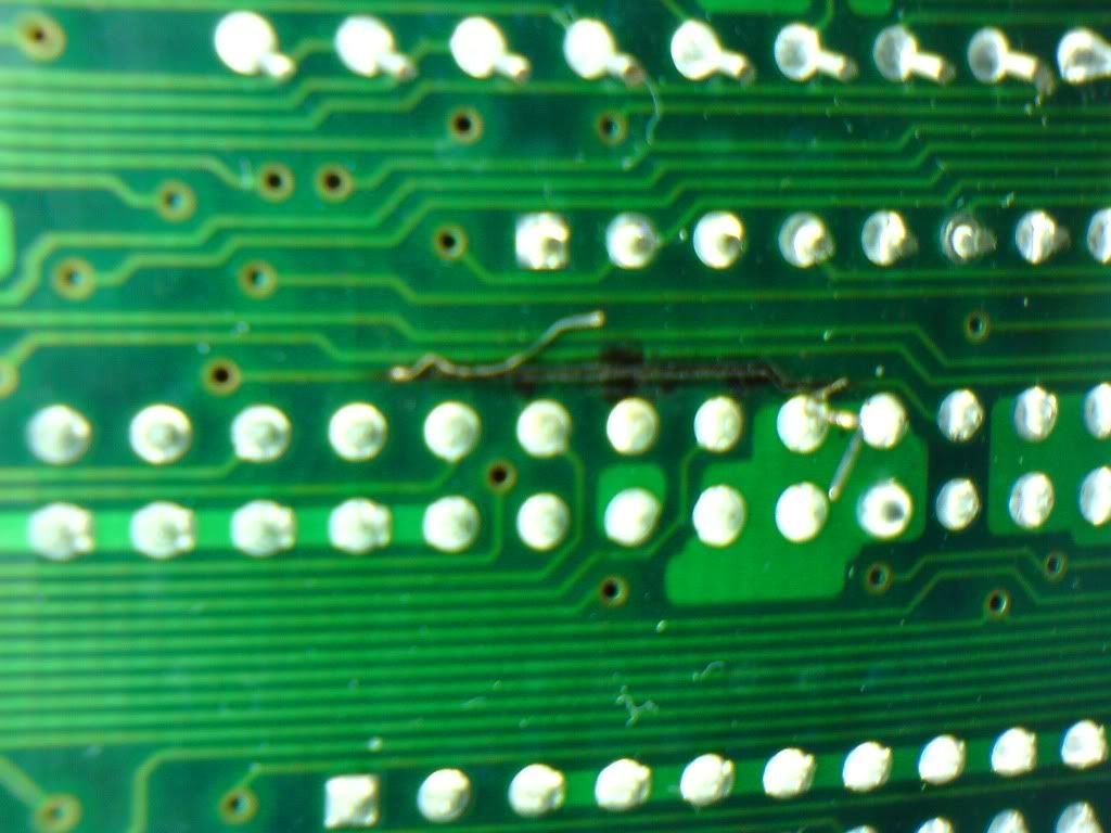
|
|
|
|
18 February 2010, 01:46
|
#12 |
|
Registered User
Join Date: Aug 2006
Location: Augusta, Georgia, USA
Posts: 552
|
Just make a jumper wire between the start and end of the trace, using the easiest places to solder. Burned trace from SCSI connector could be current drawing from a device, or a cable plug/unplug while power is applied to one or the other.
I repaired these back in the early 90's and the same thing would happen to people with lots of external devices. There is a diode on the top of the board that is supposed to keep power from coming into the SCSI interface, but it can fail closed and allow this (and burn traces). |
|
|
|
18 February 2010, 02:01
|
#13 |
|
Precious & fragile things
Join Date: Feb 2009
Location: Victoria, Australia
Posts: 1,946
|
Good find, usually it's not so easy to fault.
|
|
|
|
18 February 2010, 02:29
|
#14 |
|
Brosol
Join Date: Jan 2010
Location: Vancouver, BC, Canada
Posts: 85
|
Before the A3640 install, I was using a exterinal DB-25 SCSI terminator else SCSI devices wouldn't boot.
Hopefully this is the only problem but I wonder how the A3640 (if defective) installation was the cause. The barebone setup had no SCSI devices connected. Was my int2 mod the culprit? My modding confidence is pretty low right now.....
|
|
|
|
18 February 2010, 05:18
|
#15 |
|
Brosol
Join Date: Jan 2010
Location: Vancouver, BC, Canada
Posts: 85
|
It seems its beyond my skills & tools level to do this repair. I don't notice where else I can solder a jumper starting from Pin 26 to other location besides the through hole. I tried to solder a jumper to through hole but its too small. I have the wrong kind of wire and its too thick. I ordered a silver conductive glue syringe and hope to use it fill in the trace valley and build a trace line.
http://cgi.ebay.ca/ws/eBayISAPI.dll?...=STRK:MEWNX:IT Hope this will work. |
|
|
|
18 February 2010, 11:09
|
#16 |
|
Precious & fragile things
Join Date: Feb 2009
Location: Victoria, Australia
Posts: 1,946
|
For future reference, what you need for this type of repair is called mod wire. The small hole you desribe is called a via, to solder to that, usually you need to ***gently*** run a sharp blade around the edge to get rid of any solder resist ( the green stuff ) and then using a fine tipped iron, solder from there.
|
|
|
|
18 February 2010, 12:25
|
#17 |
|
Brosol
Join Date: Jan 2010
Location: Vancouver, BC, Canada
Posts: 85
|
I don't have precision soldering repair tools like the fine tipped iron or mod wire just crude basic Radio Shack stuff.
Thank You everyone for their help and tips.  If successful I might post more pics as a helpful reference to others. |
|
|
|
18 February 2010, 12:27
|
#18 | |
|
Thalion Webshrine
Join Date: Jan 2004
Location: Oxford
Posts: 14,461
|
Quote:
But if there was any kind of short between power and ground you'll need to buzz it through after the repair to ensure it does not happen again when you restore the power. A broken termination power wire does not sound to me like it will be the end of your repair. But I hope it is. |
|
|
|
|
18 February 2010, 20:39
|
#19 |
|
Brosol
Join Date: Jan 2010
Location: Vancouver, BC, Canada
Posts: 85
|
I was feeling more confident and impatient for the repair pen to arrive. Initially I couldn't find an alternate spot to solder a jumper from SCSI PIN 26 but I had a hunch. I used a multimeter as continuity tracer to find the alternate solder point. I found one in good spot and soldered the jumper end to a pin from a SCSI terminator strip socket.
Now the system boots up and seems to run ok! Yay!! I tried to install the A3640 again but it still does not work....this time no damage. Perhaps the A3640 is dead or it just doesn't like my A3000 DMAC-02 and RAMSEY-04 combo. I still suspect my int2 mod which I removed was the culprit somehow. 1st Jumper Repair Test looks messy, did a better job later  This image has been resized. Click this bar to view the full image. The original image is sized 1024x768. This image has been resized. Click this bar to view the full image. The original image is sized 1024x768.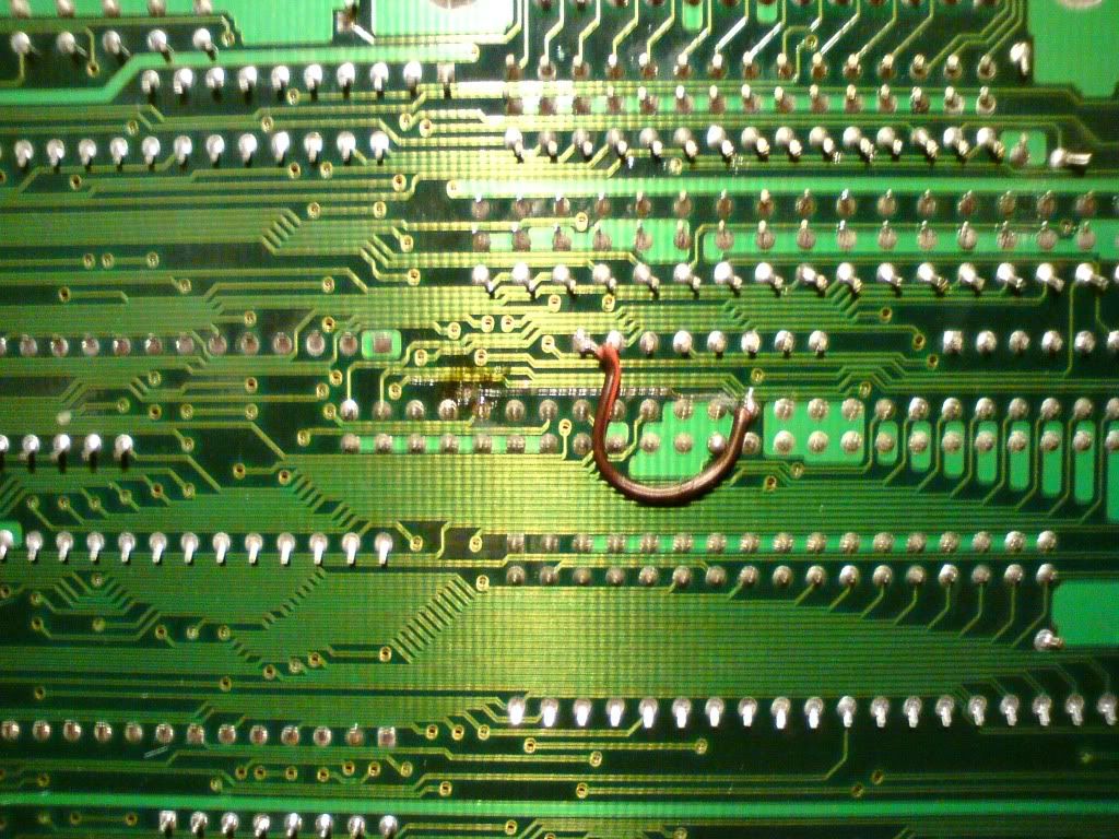 The mess, A3000 scsi to SCSI-IDE Bridge to IDE-CF adapter to 4gig CF card, it boots! This image has been resized. Click this bar to view the full image. The original image is sized 1024x768.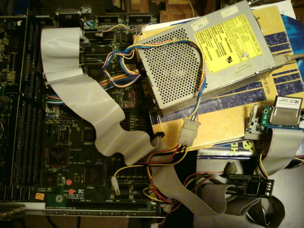 System Working Again This image has been resized. Click this bar to view the full image. The original image is sized 1024x768.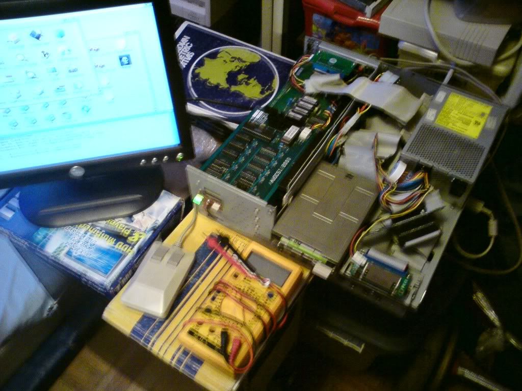 Front IDE-CF Adapter, SCSI ID 2 This image has been resized. Click this bar to view the full image. The original image is sized 1024x768.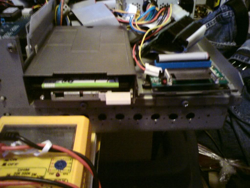 Rear IDE-CF adapter, SCSI ID 3, TOP VIew This image has been resized. Click this bar to view the full image. The original image is sized 1024x768.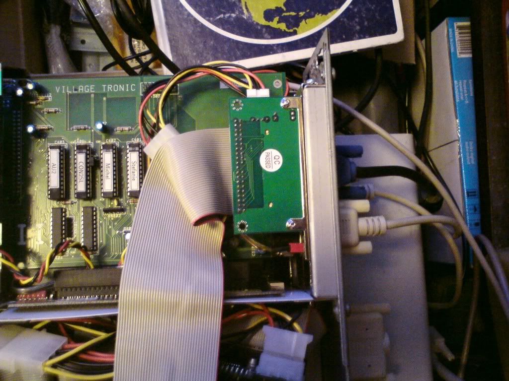 IDE-CF adapter-SCSI ID 3, Picasso II, Exhaust Fan, Ext SCSI Terminator, PAL/NTSC Toggle, UDMA 4gig CF This image has been resized. Click this bar to view the full image. The original image is sized 1024x768.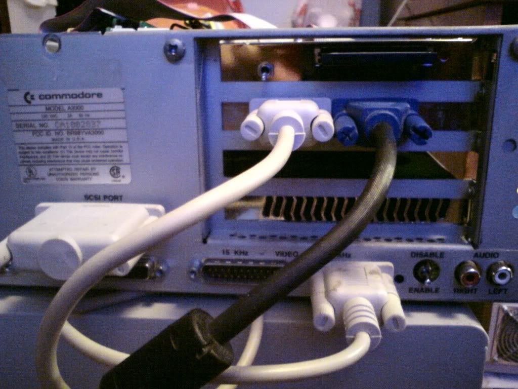 Rear IDE-CF Adapter, Picasso II, Blower Exhaust fan, AdSCSI 2000 This image has been resized. Click this bar to view the full image. The original image is sized 1024x768.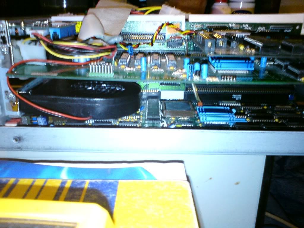
Last edited by Brosol; 18 February 2010 at 23:14. |
|
|
|
18 February 2010, 23:54
|
#20 |
|
Thalion Webshrine
Join Date: Jan 2004
Location: Oxford
Posts: 14,461
|
I am glad it worked out for you in the end.
Are you going to restore the INT2 mod before reassembly or leave it for the time being? Might be worth checking the condition and orientation of the capacitors on your A3640. Sometimes they are fitted backwards and degrade over time. Take a look at them and if they are fitted backwards or there is any leakage or bulging then that might be why it does not work. http://amiga.serveftp.net/A3640_capacitor.html Last edited by alexh; 19 February 2010 at 00:01. |
|
|
| Currently Active Users Viewing This Thread: 1 (0 members and 1 guests) | |
| Thread Tools | |
 Similar Threads
|
||||
| Thread | Thread Starter | Forum | Replies | Last Post |
| Overclock A3640 in an A3000 | Sandman | support.Hardware | 0 | 16 January 2012 21:17 |
| A4000 boots to flashing yellow screen | OverDose | support.Hardware | 6 | 30 March 2011 09:11 |
| KX Light Install doesn't boot from HD/LiveCD boots very well ?? | gerograph | support.Amiga Forever | 9 | 02 February 2011 22:05 |
| Boots to Green screen | Pacer238 | support.Hardware | 3 | 05 January 2006 08:34 |
|
|


