
|
 11 August 2022, 12:46
|
#1 |
|
Registered User
Join Date: Jun 2019
Location: AUS
Posts: 27
|
A1200 RGB no longer working
Hi all,
I have an Amiga A1200 board which I've had for about a week, I was actually repairing external floppy drives and using this board during testing. Last night I ran xcopy to check a drive and left it running for about 20 mins or so and when I returned there was a black screen. After a power off and power back on, the screen was up once again and this time I ran Amiga Test Kit and while it was on after about 10 mins the screen went off again. The system still appeared to be responsive, rebooting appeared to read the disks etc. I thought perhaps heat was causing the issue, so I left it until today however it still remains a blank screen. I hooked up the composite cable today and the image is working, so it appears that the issue is directly to do with the RGB signal? I have since been trying to figure out what to check for, so far I have checked for 5V on pin 23 and 12V on pin 22 on the Amiga RGB port. These votages are present. The Amiga board is a REV 1B There are a few wires on the board, I would guess this is factory. There is one on the V DAC chip, grounding out pin 16 [REF WHITE] to pins 20 & 21 [GND]. Everything looks fine, no signs of corrosion on the board. Any suggestions on what to test for? I've measured many of the resistors around the port and nothing stands out as high that I've found so far. Cheers |

|
|
11 August 2022, 14:58
|
#2 |
|
Registered User
Join Date: Jun 2009
Location: Dublin, then Glasgow
Posts: 6,334
|
The DAC output is also used for the composite, so there's not an awful lot that would affect all three colours at the same time. What are you connecting the RGB output to? The sync signals are a possibility - they could also be missing from the cable you're using.
|
|
|
|
11 August 2022, 15:23
|
#3 |
|
Registered User
Join Date: Jun 2019
Location: AUS
Posts: 27
|
Hi Daedalus,
Yes good points, sorry I should have included this detail in my original post, so the cable is confirmed to be ok - I dug out my Amiga 600 to confirm there was nothing wrong with the cable / setup. I'm using a scart cable with a OSSC and all is still good with the A600 video through it. So I believe it is most likely an issue with the A1200 specifically with RGB/Signal. I also like your thoughts of how it seems unlikely all colours would drop at once too, so I should turn the focus on the sync signals as you suggested.. would that be a case of measuring specific resistors and capacitors? |
|
|
|
11 August 2022, 15:38
|
#4 |
|
Registered User
Join Date: Jun 2009
Location: Dublin, then Glasgow
Posts: 6,334
|
The RGB signals are all separate from the DAC to the port. There are no components that they all have in common, so the only way for all of them to fail simultaneously is for three resistors, capacitors or diodes to all fail at exactly the same time. Which is unlikely, as you can imagine. However, if the sync signal is missing, it's usually taken as "no signal" by a device, and will result in a loss of image with just a single signal failing. SCART uses the composite sync signal, so it's worth checking that. It's much easier to check with an oscilloscope to see if it's doing the correct thing and that the buffer chip is working, but without that you can still check the continuity of the traces and the pull-up resistor. Another thing that I've seen a few times is a small ceramic capacitor failing short, which can kill a signal off. So check for resistance to ground of the signal too in case that's the failure.
|
|
|
|
11 August 2022, 16:02
|
#5 |
|
old bearded fool
Join Date: Jan 2010
Location: Bangkok
Age: 56
Posts: 775
|
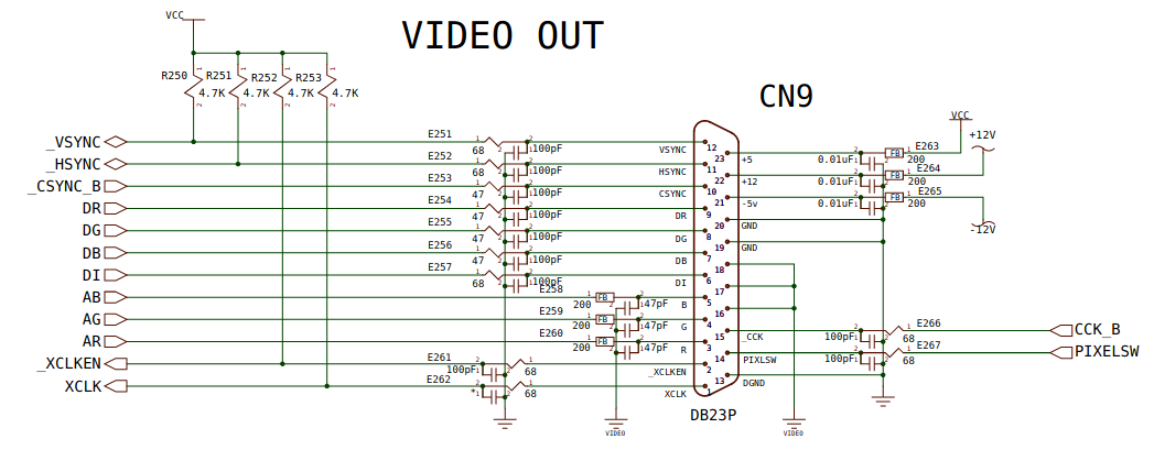
Check the resistor E253 (47 Ohm) on the path of CSYNC signal (pin 10), it can be damaged due to capacitor leakage. This resistor is close to the actual RGB/Video port on the motherboard.
 EDIT: I noticed now this was one of the suggestions from Daedalus, but with a bit more detail, so perhaps useful. Last edited by modrobert; 18 February 2024 at 17:18. Reason: Read all the replies. |
|
|
|
12 August 2022, 12:46
|
#6 |
|
Registered User
Join Date: Jun 2019
Location: AUS
Posts: 27
|
Thanks guys, I have been doing some more testing.
The composite sync is indeed missing from the Video Port (pin 10) Which comes from E253R, which is measuring correctly at 47ohms This seems to come from U32 (pin 14 _CSYNC_B) and there is no signal here. On the other side of U32 (at pin 6 _CSYNC) there is a signal. This is making me believe that the problem could be U32? I measured all the pins at U32 - here are the results: pin 1 [VIDEO] = no signal - should this have a signal? pin 2 [_RST] = high 4.5v pin 3 [DI] = signal pin 4 [CCK] = signal pin 5 [DB (blue)] = signal pin 6 [_CSYNC] = signal pin 7 [DG (green)] = signal pin 8 signal pin 9 [DR (red)] = signal pin 10 [VIDEOGND] pin 11 signal pin 12 [PIXELSW] = no signal pin 13 signal pin 14 [_CSYNC_B] = no signal - is this the issue? pin 15 signal pin 16 [CCK_B] = no signal pin 17 signal pin 18 [_RESET] = 2v pin 19 signal pin 20 [VCC] = 5v Suggestions from here would be appreciated 
|
|
|
|
12 August 2022, 13:06
|
#7 |
|
Registered User
Join Date: Jun 2009
Location: Dublin, then Glasgow
Posts: 6,334
|
Progress
Okay, U32 could certainly be the problem. That chip has two separate parts, each enabled by a separate input. Pin 1 enabled the first block of buffers, and is the critical one. If that's low, then the outputs should be enabled, however it looks like the outputs from that section (pins 12, 14, 16 and 18) are disabled. So long as pin 1 is definitely connected to ground, I would say that chip is the problem and should be changed. It's a cheap and readily available part, but you should only change it yourself if you have the right skills and equipment for doing SMT work.The first thing to check though is that pin 1 is really connected to ground (it's labelled Video because it's video ground and not logic ground), and isn't floating due to a failed via or trace. If it's floating, you might still get no signal reading on a logic probe but it will disable the chip's output. That chip also buffers the /Reset signal, and that sitting at around 2V is uncomfortably close to no-man's land in terms of logic. I wouldn't be surprised to see spontaneous resets because of that issue. It's most likely this is also caused by the same issue though, so solving that will likely solve it all. |
|
|
|
12 August 2022, 13:51
|
#8 |
|
Registered User
Join Date: Jun 2019
Location: AUS
Posts: 27
|
Thanks again Daedalus, and for that explaination which makes a lot of sense.
This is exciting to hear that we may have found the problem, as I can confirm pin 1 is definitely attached to video ground. Curious if jumping pin 6 to 14 would give a signal? (I haven't done this as I don't want to damage it). I won't have a problem swapping the IC, and thats so good to hear that I should be able to obtain one easily enough too! Its a good job that reset signal wasn't bringing the whole machine down otherwise I doubt I would have found out what was going on at all! |
|
|
|
12 August 2022, 14:18
|
#9 |
|
Registered User
Join Date: Jun 2009
Location: Dublin, then Glasgow
Posts: 6,334
|
Jumpering the signal might not work, depending on whether the chip outputs are active low or tri-stated in their current (probably faulty) state. If the chip's output is active low (and the /Reset level suggests this could be the case), it will pull down the signal going into the chip, which could stop the DAC (and so composite video) from working.
Having another quick look at the schematics I can see that the buffered /Reset line is actually just for peripherals. It wouldn't take the core of the machine down after all, but it could cause all sorts of weird issues by resetting hard drives etc., and could cause a reset of the machine depending on how a fitted accelerator handles resets. |
|
|
|
12 August 2022, 14:46
|
#10 |
|
Registered User
Join Date: Jun 2019
Location: AUS
Posts: 27
|
Well I just couldn't wait and took the U32 from another board and tried it out - guess what? It works!!
Thanks so much (again) for taking all this time explaining everything to me, now I just need to buy a replacement for the one I stole
|
|
|
|
12 August 2022, 15:57
|
#11 |
|
Registered User
Join Date: Oct 2012
Location: Krypton
Posts: 1,210
|
I only just saw this thread, yes the U32 is a weak link it is the same on the A600, I have replaced a few of those in the past and yes the CSYNC not present is typical of the U32
|
|
|
|
13 August 2022, 01:38
|
#12 |
|
Registered User
Join Date: Jun 2019
Location: AUS
Posts: 27
|
Thanks supaduper,
for anyone else with the same issue I believe the replacement IC is a HCT244 Line Driver / Buffer. Hope this helps someone
|
|
|
|
13 August 2022, 13:25
|
#13 |
|
MI clan prevails
Join Date: Jul 2010
Location: Belgrade, Serbia
Posts: 1,443
|
It does
Are these the correct parts? Link 1 : https://www.ebay.de/itm/223101246910...wAAOSwajVUS3z9 Link 2: https://www.ebay.de/itm/354086467611...sAAOSwavtfp~o6 Link 3: https://www.ebay.de/itm/225089485230...8AAOSwvjdZXffX Link 4: https://www.ebay.de/itm/284790891329...wAAOSwvqRiWNIi I also see a lot of A / DW / T variants. What's the deal with those? Last edited by Lord Aga; 13 August 2022 at 15:43. |
|
|
|
14 August 2022, 10:47
|
#14 |
|
Registered User
Join Date: Jun 2019
Location: AUS
Posts: 27
|
I believe they are all correct, the different markings are most likely due to different manufacturers etc. Hopefully someone can confirm this.
The last one (Link 4) is a slightly narrower package / version of it, it'll still fit on the pads fine though. |
|
|
|
15 August 2022, 10:58
|
#15 |
|
Registered User
Join Date: Jun 2009
Location: Dublin, then Glasgow
Posts: 6,334
|
The letter(s) after the 244 typically designate the package. This can vary from manufacturer to manufacturer, but there's a general consensus with most. D is SOIC, DW is wide SOIC (though sometimes these are also just designated D too). Wide SOIC is probably the most common, and is the one used in the 1200, though in many positions the pads are suitable to take standard width SOIC.
Beyond those, any other package won't fit. For example, N is DIP/Through hole, T can be TSSOP or TQFP, and other variants of D* (e.g. DB) are typically smaller with tighter pitches. |
|
|
|
18 August 2022, 10:35
|
#16 |
|
Registered User
Join Date: Jun 2019
Location: AUS
Posts: 27
|
Finished photo: old faulty chip sat on anti static bag. Now I just need to recap the board.
|
|
|
|
19 August 2022, 13:02
|
#17 |
|
MI clan prevails
Join Date: Jul 2010
Location: Belgrade, Serbia
Posts: 1,443
|
Thaks for the pic
Will come in handy once I get to it! |
|
|
|
01 September 2022, 06:57
|
#18 |
|
Registered User
Join Date: Oct 2012
Location: Krypton
Posts: 1,210
|
I have a few spare HCT244 Line Driver / Buffers so if anyone wants one email me
Last edited by supaduper; 01 September 2022 at 14:09. |
|
|
| Currently Active Users Viewing This Thread: 1 (0 members and 1 guests) | |
| Thread Tools | |
 Similar Threads
|
||||
| Thread | Thread Starter | Forum | Replies | Last Post |
| Cd audio no longer working? | amigang | support.WinUAE | 6 | 08 September 2020 14:30 |
| ICD AdIDE HD no longer working | B14ck W01f | support.WinUAE | 6 | 26 November 2017 03:03 |
| FS UAE on Mac no longer working | edd_jedi | support.FS-UAE | 3 | 04 January 2014 18:18 |
| Final Writer no longer working? | trydowave | support.Apps | 23 | 15 December 2013 22:14 |
|
|


