
|
 16 June 2020, 21:51
|
#1 |
|
Registered User
Join Date: Jun 2020
Location: Kent / USA
Posts: 21
|
Need help diagnosing my PAL Amiga 500+
Hi gang. About a month ago I bought an Amiga 500+ off eBay. It had a battery that exploded, but didn't appear to have too wide-spread of damage. I've managed to clean up almost all the corrosion and bodge a couple traces that were broken. However, I still can't get my poor Amiga to fire up successfully. Work I've done on it so far:
1. Replaced all capacitors on the board. 2. Socketed and replaced U12 due to heavy corrosion on the pins 3. Socketed and replaced U38 and U39 as part of trying to resolve serial issues I'll explain below 4. Verified Paula, Gary, Odd CIA, and Even CIA all operate well in an existing A2000 I have access to. 5. Verified all expected traces connecting Chip RAM, Agnus, CPU, Paula, both CIAs, ROM, and the serial port have conductivity using my multimeter. 6. Reflowed the serial port 7. Verified there are no shorts at the power supply connection port (implying none of the rails on the board are shorting either) Despite this I get a green screen when attempting to boot the kickstart ROM and the following when attempting to boot with a DiagROM: Serial output: [00][1B]gs5ra aa>fau b tDA And the following on my monitor: 1. A flickering red screen https://drive.google.com/uc?export=v...cLmLyddgUFg8He 2. A solid blue screen https://drive.google.com/uc?export=v...We9_1RMhxdSfLp 3. A solid light grey screen https://drive.google.com/uc?export=v...cDRBr4VXSNzVzo I'm kinda stumped what the problem could be. I figure it's either: 1. A bad board (perhaps a short somewhere) 2. A bad Agnus 3. Bad Ram Any suggestions on how to further diagnose? Last edited by SamBushman; 16 June 2020 at 22:18. |

|
|
17 June 2020, 01:28
|
#2 |
|
Thalion Webshrine
Join Date: Jan 2004
Location: Oxford
Posts: 14,337
|
https://www.amigalove.com/viewtopic.php?t=324
I'd say (1) you've got trace damage somewhere. Possibly vias going between the top and bottom of the board? Start at the kickstart ROM and trace address and data lines back to the CPU and the chip selects from the custom chips? ROMEN signal (comes from Gary?) High res photos of the board, top and bottom, especially around the battery might help. |
|
|
|
17 June 2020, 02:56
|
#3 |
|
Registered User
Join Date: Jun 2020
Location: Kent / USA
Posts: 21
|
Thanks for the suggestions so far. I'll recheck those tonight. Also, here are some images of the board:
https://drive.google.com/uc?export=v...3JBHGlzBNEZDwy https://drive.google.com/uc?export=v...BH5Fx8BEg06S2K https://drive.google.com/uc?export=v...FPVP98M1BRnr49 https://drive.google.com/uc?export=v...3l2OSCsnEvR4xB https://drive.google.com/uc?export=v...tF8cbXf-Aj_DT4 |
|
|
|
17 June 2020, 08:55
|
#4 |
|
Registered User
Join Date: Dec 2018
Location: UK
Posts: 1,715
|
Looking at the pictures, there is still a lot of battery damage - it needs to be removed and cleaned up and the traces repaired. It is likely that one or more of the traces are broken or high resistance and need repairing and/or re-tinning.
Last edited by solarmon; 17 June 2020 at 09:01. |
|
|
|
17 June 2020, 14:30
|
#5 | |
|
Registered User
Join Date: Feb 2007
Location: Melbourne, Australia
Age: 41
Posts: 3,772
|
Quote:
|
|
|
|
|
22 June 2020, 03:32
|
#6 |
|
Registered User
Join Date: Jun 2020
Location: Kent / USA
Posts: 21
|
Hi gang, sorry for the long delay in reply. I've been testing traces on my board. I DID find a single broken trace connecting pin 18 of U9 (the CLOCK IC) to the resistor/diode blob next to the battery terminals. I installed a bodge wire to restore connectivity, but no change to behavior.
I've been testing all the components around the "splash zone" of the battery corrosion. I also tested all the pins on Gary (including the ROMEM line, address, and data lines). All appear to be connected and I've detected no unexpected shorts on Gary's pins. I've documented the resistance measured. Most traces are below 0.5 Ohms. Everything is below 1 Ohm. I don't know if any of these readings are wildly out of spec. Any advice would be appreciated. Thanks again for your help so far! Trace resistances ROMEM -> R114 0.22 Ohms R111 -> U13 Pin 11 0.12 Ohms E106 -> R105 0.23 Ohms E106 -> Ground 0.05 Ohms R105 -> U33 Pins 2, 3 0.16 Ohms E107 -> ground 0.07 Ohms R916 -> JP9 0.13 Ohms E102 -> JP9 via 0.08 Ohms R103 -> U12 Pin 1 0.1 ohms U12 Pin 1 -> U12 Pin 19 0.05 Ohms R103 -> U10 Pin 1 0.17 Ohms U10 Pin 1 -> U10 Pin 19 0.05 Ohms R101 -> CPU Pin 10 0.31 Ohms R112 -> U11 Pin 1 0.18 Ohms R113 -> U11 Pin 1 0.13 Ohms R915 -> via near battery 0.05 Ohms R915 -> U9 Pin 2 0.2 Ohms R915 -> VCC 0.15 Ohms R102 -> clock 0.23 Ohms C12 -> VCC, Ground 0.8 Ohms Gary Gary Pin 1 -> Ground 0.08 Ohms R102 -> Gary Pin 2 0.11 Ohms R112 -> Gary Pin 3 0.11 Ohms Gary Pin 4 -> R113 0.08 Ohms Gary Pin 5 -> RP501 Pin 5 0.19 Ohms Gary Pin 5 -> JP1, Q711 0.12 Ohms Gary Pin 6 -> VCC 0.07 Ohms Gary Pin 7 -> EvenCIA Pin 17 0.14 Ohms Gary Pin 8 -> Paula Pin 39 0.17 Ohms Gary Pin 9 -> Paula Pin 38 0.17 Ohms Gary Pin 10 -> Agnus Pin 51 0.28 Ohms Gary Pin 10 -> CPU Pin 8 0.35 Ohms Gary Pin 11 -> RP101 Pin 6 0.06 Ohms Gary Pin 11 -> Agnus Pin 52 0.32 Ohms Gary Pin 11 -> CPU Pin 7 0.35 Ohms Gary Pin 12 -> Agnus Pin 22 0.3 Ohms Gary Pin 12 -> CPU Pin 9 0.48 Ohms Gary Pin 12 -> EvenCIA Pin 22 0.11 Ohms? Gary Pin 12 -> OddCIA Pin 22 0.18 Ohms Gary Pin 13 -> Agnus Pin 24 0.19 Ohms Gary Pin 13 -> CPU Pin 6 0.33 Ohms Gary Pin 14 -> CPU Pin 12 0.24 Ohms gary Pin 14 -> RP104 Pin 6 0.3 Ohms Gary Pin 15 -> Agnus Pin 20 0.19 Ohms Gary Pin 16 -> EvenCIA Pin 13 0.21 Gary Pin 16 -> Floppy Pin 10 0.23 ?Gary Pin 17 -> VCC 0.08 Ohms ?Gary Pin 18 -> Agnus Pin 23 0.18 Ohms Gary Pin 19 -> Agnus Pin 19 0.19 Ohms? Gary Pin 20 -> Agnus Pin 25 0.22 Ohms R114 -> Gary Pin 21 0.1 Ohms Gary Pin 22 -> U9 Pin 8 0.17 Ohms? Gary Pin 22 -> RAMExp Pin 49 0.54 Ohms Gary Pin 23 -> U9 Pin 10 0.24 Ohms Gary Pin 23 -> RAMExp pin 50 0.21 Ohms Gary Pin 24 -> Ground 0.05 Ohms R111 -> Gary Pin 25 0.07 Ohms E106 -> Gary Pin 26 0.07 Ohms Gary Pin 26 -> R105 0.19 Ohms Gary Pin 26 -> U33 Pin 2, 3 0.22 Ohms Gary Pin 27 -> E107 0.09 Ohms Gary Pin 27 -> Paula Pin 29 0.13 Ohms? Gary Pin 27 -> R104 0.13 Ohms ?Gary Pin 27 -> U33 Pin 10, 11 0.22 Ohms? Gary Pin 28 -> E108 0.07 Ohms? Gary Pin 28 -> U35 Pin 15 0.24 Ohms? Gary Pin 28 -> Paula Pin 28 0.13 Ohms? Gary Pin 28 -> R103 0.12 Ohms? Gary Pin 28 -> U33 Pin 5, 6 0.21 Ohms? Gary Pin 28 -> Denise Pin 36 0.22 Ohms? Gary Pin 28 -> U41 Pin 6 0.26 Ohms Gary Pin 29 -> CN15 Pin 2 0.13 Ohms ?Gary Pin 29 -> RP104 Pin 9 0.31 Ohms ?Gary Pin 30 -> RP101 Pin 9 0.08 Ohms Gary Pin 30 -> OddCIA Pin 2 0.16 Ohms Gary Pin 31 -> CN15 Pin 3 0.12? Ohms Gary Pin 31 -> RP104 Pin 8 0.31 Ohms Gary Pin 32 -> JP7A Pin 2 0.1 Ohms? Gary Pin 32 -> JP7B Pin 3 0.23 Ohms? Gary Pin 32 -> RP501 Pin 9 0.25 Ohms Gary Pin 33 -> RP105 Pin 8 0.08 Ohms? Gary Pin 33 -> CPU Pin 45 0.22 Ohms? Gary Pin 33 -> ROM Pin 33 0.26 Ohms ?Gary Pin 33 -> Agnus Pin 76 0.3 Ohms Gary Pin 34 -> Agnus Pin 77 0.19 Ohms? Gary Pin 34 -> ROM Pin 2 0.36 Ohms ?Gary Pin 34 -> CPU Pin 46 0.29 Ohms? Gary Pin 35 -> Agnus Pin 59 0.25 Ohms? Gary Pin 35 -> ROM Pin 1 0.3 Ohms? Gary Pin 35 -> CPU Pin 47 0.3 Ohms? Gary Pin 36 -> Agnus Pin 35 0.19 Ohms ?Gary Pin 36 -> ROM Pin 42 0.27 Ohms? Gary Pin 36 -> CPU Pin 48 0.28 Ohms? Gary Pin 37 -> CPU Pin 50 0.26 Ohms ?Gary Pin 38 -> CPU Pin 51 0.28 Ohms? Gary Pin 39 -> CPU Pin 52 0.28 Ohms Gary Pin 40 -> Ground 0.08 Ohms? Gary Pin 41 -> Agnus Pin 16 0.29 Ohms Gary Pin 41 -> CPU Pin 18 0.30 Ohms? Gary Pin 42 -> CPU Pin 17 0.29 Ohms Gary Pin 43 -> R101 0.09 Ohms Gary Pin 44 -> U36 Pin 9 0.18 Ohms? Gary Pin 45 -> U36 Pin 5 0.17 Ohms? Gary Pin 46 -> U36 Pin 3 0.19 Ohms ?Gary Pin 47 -> U36 Pin 1 0.2 Ohms ?Gary Pin 48 -> VCC 0.35 Ohms?? RP105 10 -> Ground 0.09 Ohms 9 -> isolated 8 -> Gary Pin 33 0.09 Ohms 7 -> Gary Pin 34 0.09 Ohms, U12 via 0.13 Ohms 6 -> Gary Pin 35 0.09 Ohms 5, 4, 3, 2 -> Gary Pins 0.09 Ohms 1 -> VCC 0.14 Ohms JP7A 3 -> Ground 0.03 Ohms 2 -> JP7B-1 0.2 Ohms 1 -> Memory Exp Via 0.15 Ohms U12 Pin 1 -> R113 0.07 Ohms? Pin 1 -> Pin 19 0.06 Ohms ?Pin 1 -> U10 Pin 1 0.09 ?Pin 1 -> U10 Pin 19 0.12? Pin 2 -> ROM Pin 15 0.23 Ohms ?Pin 2 -> U13 Pin 2 0.05 Ohms ?Pin 2 -> EvenCIA Pin 33 0.2 Ohms ?Pin 2 -> CPU Pin 61 0.23 Ohms ?Pin 2 -> RP108 Pin 9 0.24 Ohms? Pin 3 -> U13 Pin 18 0.1 Ohms? Pin 3 -> Paula Pin 42 0.21 Ohms ?Pin 3 -> Agnus Pin 83 0.13 Ohms? Pin 3 -> RP109 Pin 9 0.19 Ohms ?Pin 3 -> U19 Pin 1 0.27 Ohms? Pin 3 -> U23 Pin 1 0.25 Ohms? Pin 3 -> Denise Pin 40 0.32 Ohms? Pin 4 -> EvenCIA Pin 32 0.19 Ohms? Pin 4 -> U13 Pin 5 0.11 Ohms? Pin 4 -> ROM Pin 17 0.28 Ohms? Pin 4 -> CPU Pin 60 0.22 Ohms? Pin 4 -> RP108 Pin 3 0.21 Ohms? Pin 5 -> U13 Pin 17 0.07 Ohms ?Pin 5 -> Denise Pin 41 0.29 Ohms Pin 5 -> Paula Pin 43 0.15 Ohms ?Pin 5 -> Agnus Pin 84 0.12 Ohms ?Pin 5 -> RP111 Pin 9 0.15 Ohms ?Pin 5 -> U19 Pin 19 0.24 Ohms ?Pin 5 -> U23 Pin 19 0.24 Ohms ?Pin 6 -> EvenCIA Pin 31 0.17 Ohms Pin 6 -> U13 Pin 6 0.08? Ohms Pin 6 -> ROM Pin 19 0.3? Ohms Pin 6 -> CPU Pin 59 0.21? Ohms Pin 7 -> U13 Pin 14 0.16? Ohms Pin 7 -> Paula Pin 44 0.14? Ohms Pin 7 -> Agnus Pin 1 0.12? Ohms Pin 7 -> U19 Pin 2 0.23? Ohms Pin 7 -> U23 Pin 2 0.23? Ohms Pin 7 -> Denise Pin 42 0.27 Ohms ?Pin 8 -> EvenCIA Pin 30 0.15 Ohms ?Pin 8 -> U13 Pin 9 0.07? Ohms Pin 8 -> ROM Pin 21 0.17 Ohms ?Pin 8 -> CPU Pin 58 0.23 Ohms ?Pin 9 -> U13 Pin 13 0.08 Ohms Pin 9 -> Agnus Pin 2 0.15 Ohms ?Pin 9 -> Paula Pin 45 0.18 Ohms ?Pin 9 -> Denise Pin 43 0.3? Ohms Pin 9 -> U19 Pin 18 0.31 Ohms ?Pin 9 -> U23 Pin 18 0.31? Ohms Pin 10 -> Ground 0.07 Ohms Pin 11 -> U13 Pin 12 0.07? Ohms Pin 11 -> ROM Pin 24 0.22 Ohms ?Pin 11 -> CPU Pin 57 0.20? Ohms Pin 11 -> EvenCIA Pin 29 0.21 Ohms ?Pin 12 -> U13 Pin 8 0.08? Ohms Pin 12 -> Agnus Pin 3 0.12 Ohms ?Pin 12 -> U18 Pin 1 0.24? Ohms Pin 12 -> U22 Pin 1 0.23? Ohms Pin 12 -> Denise Pin 44 0.26? Ohms Pin 12 -> Paula Pin 46 0.13? Ohms Pin 13 -> U13 Pin 15 0.07? Ohms Pin 13 -> ROM Pin 26 0.33 Ohms Pin 13 -> CPU Pin 56 0.2? Ohms Pin 13 -> EvenCIA Pin 28 0.18 Ohms ?Pin 14 -> U13 Pin 7 0.06 Ohms Pin 14 -> Agnus Pin 4 0.17 Ohms ?Pin 14 -> Paula Pin 47 0.14 Ohms ?Pin 14 -> Denise Pin 45 0.25 Ohms ?Pin 14 -> U18 Pin 19 0.23 Ohms Pin 14 -> U22 Pin 19 0.2? Ohms Pin 15 -> U13 Pin 16 0.05? Ohms Pin 15 -> ROM Pin 28 0.25? Ohms Pin 15 -> CPU Pin 55 0.2? Ohms Pin 15 -> EvenCIA Pin 27 0.17? Ohms Pin 16 -> U13 Pin 4 0.08 Ohms ?Pin 16 -> Agnus Pin 5 0.12? Ohms Pin 16 -> U18 Pin 2 0.25? Ohms Pin 16 -> U22 Pin 2 0.23? Ohms Pin 16 -> Paula Pin 48 0.15? Ohms Pin 16 -> Denise Pin 46 0.27? Ohms Pin 17 -> U13 Pin 19 0.09? Ohms Pin 17 -> ROM Pin 30 0.13 Ohms ?Pin 17 -> CPU Pin 54 0.24? Ohms Pin 17 -> EvenCIA Pin 26 0.21 Ohms Pin 18 -> U13 Pin 3 0.06 Ohms Pin 18 -> Agnus Pin 6 0.12 Ohms Pin 18 -> U18 Pin 18 0.26 Ohms ?Pin 18 -> U22 Pin 18 0.23 Ohms Pin 18 -> Paula Pin 1 0.16 Ohms ?Pin 18 -> Denise Pin 47 0.28 Ohms Pin 19 -> (done with pin 1)? Pin 20 -> VCC 0.12 Ohms Last edited by SamBushman; 22 June 2020 at 08:09. |
|
|
|
22 June 2020, 14:48
|
#7 |
|
_Repair_Nerd_

Join Date: Jun 2020
Location: Germany
Posts: 71
|
Please check all Traces & VIAs in marked Area's!
Often there are Problem's - renew Solder Blob's! On Top of the PCB the VIAs (Vertical Interconnect Access) looks like they are ok; on Bottom Side -> the SAME VIA have a failure Signal, or they are broken. 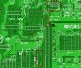 Example: It's a A600 without "Red" - at this Point -> the Line would be broken at the Pad! Similar to your Amiga -> look ath the VIAs and - i hope so - connected Traces  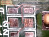
Last edited by DigitalKeeper; 22 June 2020 at 14:55. |
|
|
|
22 June 2020, 15:29
|
#8 |
|
Registered User
Join Date: Dec 2018
Location: UK
Posts: 1,715
|
@SamBushman
It looks you have put in a lot of effort in checking the traces! One thing to bear in mind is that sometimes the issue is not that the trace is broken from A to B where it is supposed to go, but because it could also be shorted to C. Thus, your continuity test between A and B will always show continuity between them, but it does not show continuity to C, unless you measure from A to C. What you could do is to try to measure for any shorts to either ground or VCC. The could be for those traces that have pull down resistors to ground or pull up resistors to VCC. Since you have DiagROM but your serial output is garbage then I would try to sort that out first - so check around the serial chips. Without output to screen and/or serial, DiagROM is useless. It is common that these serial chips, or components and traces associated with them fail and they need to be repaired/replaced. |
|
|
|
23 June 2020, 05:20
|
#9 |
|
Registered User
Join Date: Jun 2020
Location: Kent / USA
Posts: 21
|
@DigitalKeeper Thanks for the advice. I just checked the indicated VIAs. All pins and components connected to each VIA appears to connect properly and within the specs I've seen with my other trace checks. At this time I don't believe the VIAs are bad (well, to rephrase I don't think they are the cause of my present symptoms. They quite likely will need a little love to remove the last of the corrosion
).@solarmon That is a very good point. Checking the various power rails from the DC input port, I find the following: 5V (VCC) To Ground: 100.7 Ohms To -12V: No connection To +12V: No Connection -12V To Ground: No Connection +12V: No Connection +12V To Ground: No Connection Interesting, is that reading between the 5V line and Ground normal? Also, I absolutely agree with your statement about the DiagRom serial. This was the starting motivation for me checking the various traces on the board. I've traced everything back from the serial port to the custom chips and memory once already. I had found a couple breaks on U12 (which I had replaced with a socket and new IC), but bodging those pins hadn't resolved my issue. I have also already replaced U39 and U38 in case one of theme were to blame. The lack of a smoking gun has been a challenge with getting DiagRom serial to work. |
|
|
|
23 June 2020, 06:04
|
#10 |
|
Registered User
Join Date: Nov 2014
Location: NSW/Australia
Posts: 462
|
As solarmon aluded to, it looks to me like an address or data line short. Check each address lines for shorts to another, same for each data line.
|
|
|
|
23 June 2020, 11:31
|
#11 | |
|
Registered User
Join Date: Dec 2018
Location: UK
Posts: 1,715
|
Quote:
It was really whether any signal lines were shorted to any of the power lines. Sorry, I forgot you had mentioned in your first post that you replaced and socketed the serial chips. The serial chips makes use of the 12V and -12V rails, so check that these gets to U38 OK. The serial traces/signals also go to the CIA's - so you should check the CIA's and possibly swap them to see if that makes a differrence. There are also EMI components on the serial port pins that should be inspected and checked too. Last edited by solarmon; 23 June 2020 at 15:09. |
|
|
|
|
23 June 2020, 14:57
|
#12 |
|
_Repair_Nerd_
Join Date: Jun 2020
Location: Germany
Posts: 71
|
For Serial Output -> check Paula and U8 (8520)
As solarmon said - check EMI Filters, coz of short's or broken & Power at U38  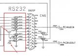 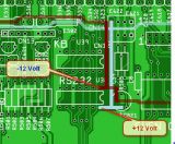 Hope it help's a little..... |
|
|
|
24 June 2020, 03:33
|
#13 | ||
|
Registered User
Join Date: Jun 2020
Location: Kent / USA
Posts: 21
|
@DigitalKeeper
Quote:
@solarmon my apologies. I had misinterpreted your suggestion. I've tested all chip pins against -12V, +12V, Ground, and +5V. All the readings appear to match the Amiga PCB Explorer. I am running with the assumption that by verifying at the chip pins, I won't need to test every via and contact point along the way. I did see that Paula Pin 34 had 0.14 Ohms to ground. That pin was labeled as "A_GND", so I assume it must be a ground line of some sort. +12V and -12V lines also appear to connect to U38 ok. Running power through the board, I see the appropriate voltage going across the pins as well. I have swapped the CIAs before and tested both in a working machine. As far as I can tell, they should be working and all traces have been tested going to them. Quote:
As for the EMI component, I don't detect any shorts and they seem connected. I don't know how to further test the components. I suppose I could just try replacing them unless there are better suggestions. One note: While checking Agnus for shorts I noticed one of the pins (in this case, all my multimeter can reach is the body of the socket pins, not the chip itself) was a little sensitive to actually reading properly (it was pin 41, one of the ground pins). I reflowed all the Agnus pins, but there was no change in behavior 
|
||
|
|
|
24 June 2020, 16:27
|
#14 |
|
Registered User
Join Date: Mar 2012
Location: Norfolk, UK
Posts: 1,153
|
OK, it looks to me like the ROM's reading fine since Kickstart gives you a greenscreen and DiagROM attempts to write to the serial port.
Since both ROMs are apparently hitting the right hardware registers to make the screen flash and serial port emit characters, I think the address lines are probably OK - or at least not the main problem. Check, double check and triple-check all the traces and vias around U10, U11 and especially U12 and U13, since (a) that's the area of worst damage, (b) you have what looks like a data bus problem, and (c) the data connection between the CPU and chipset / onboard memory goes through there. It's also possible, I suppose, that one of U10/11/12/13 is faulty? |
|
|
|
26 June 2020, 07:42
|
#15 |
|
Registered User
Join Date: Jun 2020
Location: Kent / USA
Posts: 21
|
Thanks for the suggestions robinsonb5!
An update to my investigation: I've finished checking U9, U10, U11, U12, and U13. U9 (labeled CLOCK on the board) had 3 different broken traces. I've bodged those. After that fix, all traces on all chips checked out. No pins were shorting with one another, 5V, +12V, -12V, or Ground. With the bodges to U9 there was no change in behavior. U12 had previously been replaced and socketed due to significant corrosion on the pins. U10 had less, but given how things are going I went ahead and replaced with (adding a socket). No change in behavior. I could order and replace the other ICs in this cluster I suppose. I have a small bluetooth oscilloscope that I could use to look at some of these pins during operation. However, I'm not really sure what to look for. Any thoughts on what to try next? |
|
|
|
26 June 2020, 10:17
|
#16 |
|
Registered User
Join Date: Mar 2012
Location: Norfolk, UK
Posts: 1,153
|
Do you have the facilities to burn your own ROMs?
|
|
|
|
26 June 2020, 17:39
|
#17 |
|
Registered User
Join Date: Jun 2020
Location: Kent / USA
Posts: 21
|
Not currently. Whatcha thinkin'?
|
|
|
|
26 June 2020, 20:45
|
#18 | |
|
Registered User
Join Date: Mar 2012
Location: Norfolk, UK
Posts: 1,153
|
Quote:
Just that since the CPU's own bus seems to be working (since the ROM works), the chipset / RAM bus isn't working and the point where the two join is where the worst of the corrosion happened, it would be useful to be able to put specific signals on the bus using a custom ROM. Since you have that bluetooth scope, see if you can see activity on the D0 - D4 pins on each of the RAM chips, and also pin 1 of U10, U11, U12 and U13, when you power on... |
|
|
|
|
27 June 2020, 07:00
|
#19 |
|
Registered User
Join Date: Jun 2020
Location: Kent / USA
Posts: 21
|
As a slight off topic, I had bought a Pokit Meter a couple weeks ago for this project. I just went to try it tonight and found that it has issues connecting to my android phone. Reading online, many have had that issue. Looks like I gotta explore other options for reading signals off these pins :/
As a lesson to everyone here, the Pokit Meter is not a matured product. I've seen less complaints about iOS but overall I am not impressed. Now back to the Amiga 500+........ |
|
|
|
27 June 2020, 10:57
|
#20 | |
|
Registered User
Join Date: Mar 2012
Location: Norfolk, UK
Posts: 1,153
|
Quote:
That's annoying. Hopefully you'll be able to find a better solution. (By far the cheapest diagnostic tool I have is a simple crystal radio earpiece. They're very high impedance so shouldn't affect any logic you probe with them - so much so, in fact, that you don't even need a proper return path! I just tested on my A500+ and I can just about hear some evidence of the signals on the RAM chips' data lines, and pin 1 of U10-13 just by touching the tip of the plug to the relevant pin. If I touch the barrel of the earpiece's plug with my finger at the same time I can hear it more clearly, especially if I allow my hand to touch the RF shielding at the same time. Obviously I can't tell a great deal about what's happening on the pins I'm probing, but I can verify that a signal of some sort is reaching them.) |
|
|
|
| Currently Active Users Viewing This Thread: 1 (0 members and 1 guests) | |
| Thread Tools | |
 Similar Threads
|
||||
| Thread | Thread Starter | Forum | Replies | Last Post |
| PAL/NTSC Switch for Amiga 500+ | Dew-It | Hardware mods | 1 | 16 June 2018 20:59 |
| FS: Amiga 500 Pal with boxed softwares | Nosferax | MarketPlace | 1 | 19 January 2018 19:27 |
| Amiga 500+ Pal or NTSC? | Dropcheck | support.Hardware | 28 | 16 October 2015 08:52 |
| Amiga 500 Rev6A from NTSC to PAL | chapas | support.Hardware | 8 | 15 May 2014 11:53 |
| Amiga 500 (PAL/NTSC) | gibs | Amiga scene | 0 | 04 December 2011 17:51 |
|
|


