
|
 13 February 2021, 00:17
|
#1 |
|
ex. demoscener "Bigmama"
Join Date: Jun 2012
Location: Fyn / Denmark
Posts: 1,624
|
Requesting info on video slot clocks
Is there any (C= official?) timing diagrams available for the video clock signals (CDAC, C1, C3, C4, C28O) showing the relationship of these to the digital RGB outputs of Denise/Lisa?
For instance, the RGBtoHDMI project has a jumper for selecting denise/super-denise, suggesting that they don't update the RGB outputs at the same time relative to e.g. CDAC. |

|
|
13 February 2021, 05:04
|
#2 | |
|
Registered User
Join Date: May 2020
Location: Iowa, USA
Posts: 150
|
I have some of the same questions as I ponder the Pi to HDMI circuit, too. At the moment, I don't understand the difference between Denise and Super Denise. Why can't they use the same clock signal? On c0pperdragon's board, he uses _CDAC for Denise and 7MHz for super denise. I have been looking around this site.
http://amigadev.elowar.com/read/ADCD.../node02B0.html Quote:
|
|
|
|
|
13 February 2021, 10:29
|
#3 | ||
|
ex. demoscener "Bigmama"
Join Date: Jun 2012
Location: Fyn / Denmark
Posts: 1,624
|
Hmm... I found this earlier, which seems to be straight from the horses mouth, but something's weird about the description of CDAC:
Quote:
Unfortunately, it also says this, so chances of getting such info are probably slim: Quote:
Last edited by hooverphonique; 13 February 2021 at 11:02. |
||
|
|
|
13 February 2021, 12:56
|
#4 |
|
Registered User
Join Date: Jun 2018
Location: Stockholm
Age: 48
Posts: 264
|
You can check the C= Agnus specification available on the EAB file server, check this thread below:
http://eab.abime.net/showthread.php?p=1249826 Here is what the Agnus spec says about how the inverted CDAC is created: CDAC* This clock is obtained after inverting the 7MHz clock and shifting it by 90 degrees. Oh, and the OCS Denise doesn't have CDAC connected, that pin is N/C, but it should be available on the socket pin 34 anyhow (not on rev3 mobo) I think, and also the CSync-signal isn't available on pin 32 on older A500 rev3 boards. http://amigadev.elowar.com/read/ADCD.../node023C.html Hope it helps! |
|
|
|
13 February 2021, 15:50
|
#5 | |
|
ex. demoscener "Bigmama"
Join Date: Jun 2012
Location: Fyn / Denmark
Posts: 1,624
|
Quote:
I already stumpled on that other thread, but can't find those documents on the file server.. There's no 'Commodore_Amiga' root directory. "Shifting it by 90 degrees" - yes, but in which direction? RGBtoHDMI won't work on rev 3 then, because it uses CSYNC, and CDAC for OCS denise. |
|
|
|
|
13 February 2021, 16:03
|
#6 | |
|
Registered User
Join Date: Mar 2012
Location: Norfolk, UK
Posts: 1,153
|
Quote:
I have no inside info here, but I'd assume it's shifted by delaying it; in combination with the inversion that would be a 270 degree shift, so it would then lead the 7MHz clock, consistent with the previous description. If that wasn't the intention, surely they've have shifted the raw 7MHz clock instead of inverting it first? |
|
|
|
|
13 February 2021, 16:09
|
#7 |
|
Registered User
Join Date: Jun 2018
Location: Stockholm
Age: 48
Posts: 264
|
Try here:
ftp://ftp:any@grandis.nu/~Uploads/Ba...ual-ENG%20.zip Looks like kipper2k is already on top of that rev3 issue https://github.com/c0pperdragon/Amig...ideo/issues/28 |
|
|
|
13 February 2021, 16:48
|
#8 | |
|
ex. demoscener "Bigmama"
Join Date: Jun 2012
Location: Fyn / Denmark
Posts: 1,624
|
Quote:
|
|
|
|
|
13 February 2021, 16:50
|
#9 | |
|
ex. demoscener "Bigmama"
Join Date: Jun 2012
Location: Fyn / Denmark
Posts: 1,624
|
Quote:
Thanks.. Yes, quite a long thread there... |
|
|
|
|
04 March 2021, 21:38
|
#10 |
|
ex. demoscener "Bigmama"
Join Date: Jun 2012
Location: Fyn / Denmark
Posts: 1,624
|
So I received my prototype pcb's for my attempt at a videoslot version of the RGBtoHDMI project today.
Instead of immediately populating a pcb, I dug out my oscilloscope and added some patch wires to a pcb, to measure the clock timing. So if anybody's interested, here are some screenshots with that pcb in an A4000 video slot: /C1 vs /C3 (+ math XOR) /C1 vs CDAC The relationship between /C1, /C3, and CDAC appears to be as documented elsewhere. R6 (red gun bit 6) vs CDAC Pixel transitions seem to occur 45 degrees after a CDAC transition. R6 (red gun bit 6) vs C28O (Lisa pixel clock) C28O looks really bad (reflections?), I wonder if it needs to be terminated into some characteristic impedance.. Anyway, it looks like this clock can be used to directly latch pixels at the rising edge - since I want compatibility with non-AGA machines also, it's not something I can use in general, though. I wonder if the timing of pixels (Lisa) in relation to these clocks is the same as Denise, Super-Denise, or none of them? Last edited by hooverphonique; 05 March 2021 at 14:04. |
|
|
|
05 March 2021, 04:45
|
#11 |
|
Registered User
Join Date: May 2020
Location: Iowa, USA
Posts: 150
|
I was able to get a working video slot -> Pi HDMI card working for OCS/ECS machines. It would be great to have something for the 4000 as well. You can check the schematics at https://github.com/jasonsbeer/Amiga-HDMI-Through-Hole. I'm happy to talk about any of my findings if that is of interest to you. The part I struggled with a little was recreating the 7MHz clock signal for super denise. I tried a couple iterations and both worked. Version 1.1 of my board is the more simple design.
Here's the /C1 (yellow) and /C3 (blue) signals from my A2000. 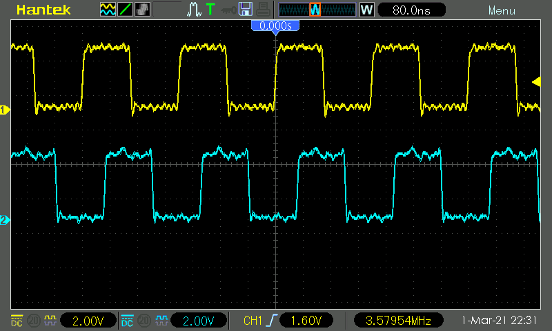
|
|
|
|
05 March 2021, 11:27
|
#12 |
|
ex. demoscener "Bigmama"
Join Date: Jun 2012
Location: Fyn / Denmark
Posts: 1,624
|
Yes, I noticed you posted an image of your board in another thread some days ago - Nice! I will star your repository and have a closer look later this weekend, but it seems you're generating 7M by xor'ing /C1 and /C3 (which should work), and alternatively use CDAC directly (just like the original c0pperdragon design) for ocs denise.
Can you confirm that the Pi is set up to use both edges on PiClk as pixel clock? I had a look at the firmware, but haven't dug deep enough (yet) to understand all of how it samples the GPIO's. And thanks for sharing :-) |
|
|
|
06 March 2021, 04:53
|
#13 | ||
|
Registered User
Join Date: May 2020
Location: Iowa, USA
Posts: 150
|
Quote:
I can only find references to the rising edge in this file. Code:
-- Shift the bits in LSB first
    process(sp_clk)
    begin
        if rising_edge(sp_clk) then
            if sp_clken = '1' then
                sp_reg <= sp_data & sp_reg(sp_reg'left downto sp_reg'right + 1);
            end if;
        end if;
    end process;

    process(clk)
    begin
        if rising_edge(clk) then
        ...
Quote:
On a side note, the firmware would need to be modified to support 24 bit color as is used in the AGA chipset. Should be possible assuming there are enough I/O lines left on the GPIO. |
||
|
|
|
06 March 2021, 05:06
|
#14 |
|
Registered User
Join Date: May 2020
Location: Iowa, USA
Posts: 150
|
Probably should ignore my comments above....I think that is code for a CPLD hat to handle 12 bit RGB on certain systems. That hat is not needed on the Amiga. Anyhow, I'm digging!
Last edited by jasonsbeer; 06 March 2021 at 05:23. |
|
|
|
06 March 2021, 05:09
|
#15 |
|
Moderator
Join Date: Jan 2002
Location: Chicago, IL
Posts: 3,375
|
@jasonsbeer
That was really faaaaast. Cool you got this working on some Amigas. |
|
|
|
06 March 2021, 11:23
|
#16 |
|
ex. demoscener "Bigmama"
Join Date: Jun 2012
Location: Fyn / Denmark
Posts: 1,624
|
If I'm not completely crazy, the clock for the flipflops is twice (14MHz) the frequency of the clock going to the Pi (PiClk), hence my assumption that it samples on both edges (to support hires).
Yes, the thing about the cpld boards is a little confusing since the c0pperdragon project doesn't use one, and RGB2HDMI never mentions using it without one (but I suppose the flipflops + xor's is a kind of cpld ;-) ). Last edited by hooverphonique; 08 March 2021 at 10:32. |
|
|
| Currently Active Users Viewing This Thread: 1 (0 members and 1 guests) | |
| Thread Tools | |
 Similar Threads
|
||||
| Thread | Thread Starter | Forum | Replies | Last Post |
| A2000 Video slot / Lighttech Scan Doubler | A2k_Newb | support.Hardware | 0 | 11 December 2019 22:27 |
| Amiga 4000 video slot, what video card to buy? ... | LOU | support.Hardware | 1 | 01 June 2018 02:13 |
| Amiga A4000 video slot pinout | alexh | support.Hardware | 14 | 29 October 2008 08:50 |
| micronik video-slot enabler+picasso IV flifi. | sebnet | support.Hardware | 18 | 06 April 2008 05:16 |
| Which slot is the video slot ? | THX1138 | support.Hardware | 13 | 21 November 2003 12:35 |
|
|


