
|
 01 January 2021, 19:48
|
#401 |
|
Registered User
Join Date: Jan 2004
Location: Yorkshire
Posts: 710
|
In case you forgot the parts that had mistakes and shouldn't be installed were the custom keyboard header section on the back, U49 and part of the programming section, luckily none of them are needed. The only other mistake was the oscillator tri-state pin being connected to ground like Commodore schematics said to do.
|

|
|
02 January 2021, 00:05
|
#402 |
|
_Repair_Nerd_

Join Date: Jun 2020
Location: Germany
Posts: 71
|
First - AWESOME - work !
 Note that Gayle can set "low" the _RST if there's something wrong with _KBReset  Means - if there is "Power Loss" - ya need +4,7Volt to determine, that the "defined state" work properly  Have a look: 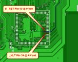 Get a small screwdriver and do a "short" between 39 & 40 for a second - look, if it's come up -> booting to kickstart - if yes - there is a problem with the reset circuit 
|
|
|
|
03 January 2021, 12:24
|
#403 |
|
Registered User
Join Date: Jan 2008
Location: United Kingdom
Age: 46
Posts: 733
|
Hi,
I checked _KBRESET, it stays low for 600ms after application of power, then goes high, this is expected operation. The _HLT signal is at logic 1, expected as it only has a pull-up resistor. I did get _RST to go to logic 1, by changing the resistor value from 4K7 to 1K. I removed the pull-up resistor, inserted my DMM, set to measure current, and observed the current flowing. There is most likely still a problem somewhere else. I can see that _AS is low, indicating the start of a cycle and _DTACK is high, this tells me a bus cycle started but did not complete. I need to check a few more signals around the MC68000 and GAYLE. I have documents on AGNUS, DENISE, GAYLE & the CIA chips, this helps me understand how things are meant to work, just reading some of them now. |
|
|
|
03 January 2021, 21:56
|
#404 |
|
_Repair_Nerd_
Join Date: Jun 2020
Location: Germany
Posts: 71
|
Sounds Good!
 Hope, ya would find the Problem... No! I'm sure
|
|
|
|
11 January 2021, 15:26
|
#405 |
|
Registered User
Join Date: Jan 2004
Location: Yorkshire
Posts: 710
|
Does the A600 with 3.1 ROM have the long delay for IDE? and if you build a board without DAC and the floppy eventually clicks away does it mean that it has passed all post checks?
edIt. right so a more detailed update. I bought a proper soldering iron a few months ago and was going to use a board as soldering practice pretty much expecting to ruin it and abandon ship but it's gone rather better than expected and I'm getting the floppy seeking noise at least after a few second delay. I still have quite a bit to do and I move like a snail though. I didn't say anything sooner in case it went badly. Last edited by Mick; 11 January 2021 at 19:13. |
|
|
|
12 January 2021, 00:14
|
#406 | |
|
Registered User
Join Date: Jan 2008
Location: United Kingdom
Age: 46
Posts: 733
|
Quote:
Kickstart 3.1 has up to 20 second delay for floppy drive before the kickstart screen shows? The A600 does not have a DAC, that's the A1200. It uses a resistor network to create the analogue video from DENISE. The analogue video signals get fed to the CXA1145 Encoder which encodes RGB to composite. You should be able to tap off C211-C213 and CYSNC and see an image on a monitor. I have a ver 1 board, 4 layer with the power nets named U12_1 and U13_1 for 0V and 5V. The processor does not startup. It starts a cycle and stalls indefinitely. It does not appear that there is a bus timeout function in GAYLE  Not sure if incorrectly fitting the ROM fried something, have to check a few parts/traces in the CPU/ROM path. I have all the correct clock signals, HSYNC and VSYNC but no video output as it has not booted. Still have a few things to try but have spent around 30 hours testing the board so far. I drilled out two vias that connected NC pins on the 68000 processor to +5V last night, that made no difference. Can you send me a link to the schematics/PCB you are using? I might merge newer schematics with the PCB I have, see what shows up as different.
|
|
|
|
|
12 January 2021, 10:05
|
#407 |
|
Registered User
Join Date: Jan 2004
Location: Yorkshire
Posts: 710
|
I want to just check everything and finalise it first, the original board should be okay schematically if you ignore the mistakes I've posted I don't know what's wrong with it.
U12_1/U13_1 was just a labeling issue due to global labels taking priority over net naming, I've fixed it and also figured out how to use multiple symbols for a part, the schematics look pro now. The Amigawiki schematics seem to have some differences to the Amiga 600 service manual that's available, some of the decoupling capacitors I think are 0.01 instead of 0.047. I've changed some of the audio values consistent with A1200 rev 2 because from what I've read they're the best for audio levels (might be wrong) because Commodore originally used too much gain(?), on early A1200 boards at least they had distortion. I need to check. The only other differences I've noticed from photos are around Agnus and are as follows: E199 - 27 ohm resistor E126R - 47 ohm resistor E127R - 47 ohm resistor EC128 - 47pF capacitor (I think this is right) EC129 - 47pF capacitor (I think this is right) If you look at photos the previous capacitors have a different colour that's same as 47pF elsewhere on the board. Also R214x/215x/216x are all 1% tolerance. I'm still unsure what value E120C should be? Last edited by Mick; 12 January 2021 at 15:14. |
|
|
|
12 January 2021, 10:13
|
#408 |
|
Registered User
Join Date: Jan 2004
Location: Yorkshire
Posts: 710
|
What's the best way to remove D-Sub connectors from an old board? I find soldering a lot easier than de-soldering.
|
|
|
|
12 January 2021, 13:22
|
#409 | |
|
-
Join Date: Jul 2003
Location: Helsinki / Finland
Age: 43
Posts: 9,865
|
Quote:
|
|
|
|
|
12 January 2021, 15:17
|
#410 |
|
Registered User
Join Date: Jan 2004
Location: Yorkshire
Posts: 710
|
Ok thanks, I'll finish it and give it a test with only D-Sub's remaining before forking out for one.
BTW thanks for the time you've put in Stedy it will have to remain one of life's mysteries. I didn't realise but PCBWay have a prototype and advanced service, I used the prototype before so it might be a manufacturing issue, apparently with the advanced service they assign you a more experienced engineer and do an electrical inspection etc. |
|
|
|
13 January 2021, 00:14
|
#411 |
|
Registered User
Join Date: Jan 2008
Location: United Kingdom
Age: 46
Posts: 733
|
Hi Mick,
Let's start with the soldering first. Sometimes, adding fresh solder makes removal easier as the flux from the fresh solder helps to melt the joint, which has potentially oxidised. I also have flux pens and a syringe of flux, just in case. If you have tried to de-solder a pin and there is still some solder left in the barrel of the PCB, you can try solder wick. If this fails, sometimes I reflow the solder joint, with fresh solder and try again. A 12mm chisel tip for de-soldering also helps as I can reflow multiple pins at once, add fresh solder, move it up and down the connector length, carefully, and with gentle force, you can remove connectors/sockets. I have an Aoyue 2702 rework station with hot air gun, electric solder sucker, soldering iron and I bought some soldering tweezers, which made lift and shift of parts so easy. I have an Antex 690D, temperature controlled solder station with a variety of tips for assembly and rework too. With regard to the non-functioning A600 PCB, I have not given up yet. Reviewing my notes from the weekend and the MC68000 datasheet, I might have seen something that fits with the various values you reported for E199, E126R, E127R, EC128 & EC129, some of the clock signals were a bit slow with their rise/fall times. I can easily tweak this and see if it has any effect. I cannot discount, at this stage, that incorrectly fitting DiagROM, could have damaged the CPU. I'll check tracks between the CPU and the ROM at the weekend. It's nice to do some digital electronics for a change, have been mainly doing analogue and power electronics the last few years. 
|
|
|
|
14 January 2021, 15:25
|
#412 |
|
Registered User
Join Date: Jan 2004
Location: Yorkshire
Posts: 710
|
There's also the differences I mentioned between some of the decoupling caps, I'm not sure if Amigawiki measured a physical board or what, they seem to have 2D schematics but I can't find them anywhere else online. The service manual is rev 1 which might explain differences but apart from these decoupling caps and U49 they look to be similar and retail boards are slightly different around Agnus.
Anyway, if anyone has an unmodified 2D board maybe they can check the following for me as I'd like to get the right values: C7, C8, C9, C29, C28A, C28B, C36, E128C, E129C and also E120C. BTW stedy I also noticed the A1200 has bigger decoupling caps for stuff like the CIA's, are they needed with a plane? Also, I found the reason you can't have Kicad parts ending with a letter is because when you split parts into multiple symbols they're listed as A, B, C etc. Last edited by Mick; 14 January 2021 at 15:37. |
|
|
|
15 January 2021, 15:38
|
#413 |
|
Registered User
Join Date: Jan 2004
Location: Yorkshire
Posts: 710
|
I've soldered everything apart from the 4 big d-subs and the joystick port (I only had 1 9-pin from planned ReAmiga build).
So I just set it up with floppy disk and some speakers and this time put a floppy in, I can confirm it's loading games and I'm getting audio (JWWS intro never sounded so good  ), I removed all of the CXA1645 stuff at the last minute to play it safe (sorry to those wanted it) so there's less chance of anything being wrong with video output but it still needs to be tested. ), I removed all of the CXA1645 stuff at the last minute to play it safe (sorry to those wanted it) so there's less chance of anything being wrong with video output but it still needs to be tested.The only video cables I seem to have that support modern displays are 23pin so it may take a while to get an electric desolder sucker thing and some converters/cables to test all of the video. |
|
|
|
15 January 2021, 16:28
|
#414 |
|
Registered User
Join Date: May 2018
Location: Germany, Baden-Wuerttemberg
Posts: 387
|
Congratulations! Have been following this thread for a while now. I admire your perseverance! :-)
|
|
|
|
19 January 2021, 17:58
|
#415 | |
|
Registered User
Join Date: Jan 2004
Location: Yorkshire
Posts: 710
|
I need to know this for finishing the schematics if anyone can help.
Quote:
|
|
|
|
|
19 January 2021, 18:22
|
#416 |
|
Registered User
Join Date: Jan 2004
Location: Yorkshire
Posts: 710
|
I can confirm video output is working, just tested composite and s-video using a HDMI converter and predictably s-video looks way better.
|
|
|
|
19 January 2021, 18:38
|
#417 | |
|
Blitter
Join Date: Aug 2017
Location: England
Posts: 50
|
Quote:
|
|
|
|
|
21 January 2021, 18:23
|
#418 |
|
Registered User
Join Date: Jan 2004
Location: Yorkshire
Posts: 710
|
I'll have to take some later, I got carried away playing Settlers.
 Bearing in mind I'm using a 4K monitor and a HDMI scaler composite seems to exhibit quite a lot of shimmering around bright/contrasting colours, I wouldn't like to play that way don't know if it's just the general quality or the scaler, also I'll try a 100ohm ferrite bead when they arrive as I stuck a 200 ohm in E231R. S-Video picture quality is solid and easily playable except that I'm getting some kind of slight ghosting/trailing effect in motion which I again presume is the scaler. It's pretty solid though and a better option than RF. RGB will always be king though.  
|
|
|
|
21 January 2021, 18:36
|
#419 |
|
Registered User
Join Date: Jan 2004
Location: Yorkshire
Posts: 710
|
Composite:
 S-Video:  Composite:  S-Video: 
Last edited by Mick; 21 January 2021 at 18:41. |
|
|
|
21 January 2021, 18:50
|
#420 |
|
Registered User
Join Date: Jan 2004
Location: Yorkshire
Posts: 710
|
I just need a bit of help now identifying the previously mentioned capacitor values so that the schematics are consistent with a retail board.
|
|
|
| Currently Active Users Viewing This Thread: 1 (0 members and 1 guests) | |
| Thread Tools | |
 Similar Threads
|
||||
| Thread | Thread Starter | Forum | Replies | Last Post |
| Legal: Amiga schematics | michaelz | support.Other | 25 | 15 March 2017 13:13 |
| First Amiga 600 FPGA Accelerator - Vampire 600 | majsta | Hardware mods | 736 | 18 July 2016 18:31 |
| aminet Clean schematics Amiga Classics | cosmicfrog | support.Hardware | 14 | 12 March 2016 20:03 |
| Amiga 2000 keyboard schematics | Brannigan | support.Hardware | 11 | 10 February 2014 08:24 |
| What if DCE donated Amiga Hardware Schematics? | Yoto | Retrogaming General Discussion | 47 | 15 May 2012 15:04 |
|
|


