
|
 02 January 2017, 08:52
|
#1 |
|
Registered User
Join Date: May 2010
Location: Helsinki, Finland
Posts: 1,341
|
PicoPSU voltage
Hi guys,
as my original Amiga power supplies slowly die away, I looked into replacements and got a 90 watt PicoPSU and Stedy's adapter to go with it. I scavenged a power cable from an old supply and built the whole contraption into a project box. Now, the concept works just fine. However, there is a problem, as the voltage delivered to the (A1200) motherboard drops significantly especially when an accelerator is connected. Under just idle load, the voltage at the PicoPSU is a nice 5.09V or so, but at the motherboard I only get about 4.65V, which is too low for stable operation. Obviously, the power cable has a fairly significant resistance and the current causes a voltage drop. I assume the real problem here is that the PicoPSU is intended to be plugged right onto the ATX power connector of a motherboard and does not need to account for this kind of thing. Is there a way to adjust the output voltage of the PicoPSU to compensate? Is there a +5V voltage sense line I could use? I know I could probably replace the power cable with a shorter/thicker one but that takes away from the convenience of the setup... Any ideas are appreciated! |

|
|
02 January 2017, 17:16
|
#2 |
|
ex. demoscener "Bigmama"
Join Date: Jun 2012
Location: Fyn / Denmark
Posts: 1,630
|
Knowing nothing about the ppsu, I'd say there must be a 5V sense signal somewhere, that you could tap into...
|
|
|
|
02 January 2017, 17:21
|
#3 |
|
Registered User
Join Date: May 2001
Location: ?
Posts: 19,646
|
Do you have a legit picoPSU or a knock-off ? I found there's a lot of knockoffs sold online that sometimes perform OK but not all times. I have landed with a few of those during the years.
I did have some issues with it powering up at all though, and the way I solved it was powering the floppy drive directly by the picoPSU, instead of the motherboard. This would jump start it right off. I don't have to do that anymore since I got Stedy's adapters, though. |
|
|
|
02 January 2017, 17:28
|
#4 |
|
Registered User
Join Date: May 2010
Location: Helsinki, Finland
Posts: 1,341
|
@hooverphonique
I tried googling around for this and it seems a sense line is more common for the 3.3V line. In any case, I'd need specific PicoPSU information... if the regulation is done inside a chip, not much I can do. @Akira It's from their own site, so at least I have no reason to believe so. And it's not doing anything unexpected, as it keeps a nice steady 5 volts when measured at the PicoPSU itself. The cable/connector is the problem and I'd need some way to increase the voltage a bit. |
|
|
|
02 January 2017, 17:37
|
#5 |
|
Registered User
Join Date: May 2001
Location: ?
Posts: 19,646
|
Oh I get it, sorry, I didn't understand that bit, I thought the picoPSU itself dropped output when powered on! I haven't had such problems, I wonder how your setup looks like to create this issue.
I have mine really close to the PSU jack and the cables I am using are rather short. |
|
|
|
02 January 2017, 18:06
|
#6 |
|
Registered User
Join Date: May 2010
Location: Helsinki, Finland
Posts: 1,341
|
Yeah, I'm basically trying to emulate the original external power supply so I could use this with different systems as needed. The power cord is the original so it's pretty long. I guess the original PSU provided extra voltage to compensate for the loss. I'll need to take some measurements.
|
|
|
|
02 January 2017, 18:32
|
#7 |
|
Unregistered User
Join Date: Sep 2012
Location: Copenhagen / DK
Age: 43
Posts: 4,190
|
I also see a not insignificant voltage drop when using the normal Amiga PSU cable. With an unexpanded Amiga it is not that much, maybe ~0.15V which is mostly compensated for with many PSUs supplying ~5.1V, however when you add an accelerator, Indivision etc. then the current increases and the voltage drop could exceed 0.3V and then it can become a problem. It should be possible to modify the PSU to increase the voltage, however I don't know how this is done specifically for your PSU.
|
|
|
|
02 January 2017, 19:43
|
#8 |
|
Registered User
Join Date: May 2010
Location: Helsinki, Finland
Posts: 1,341
|
@demolition
Yeah, I actually found your thread from a few years back. My build is similar to yours. I probed around a bit with the multimeter and looks like the resistance of the power cable is close to 0.11 Ω. Calculating for a generous 4.5 A, we are looking at a half a volt or so of voltage drop because of the cable. If the PSU could be adjusted to 5.25 V, then it should still keep the mobo supplied at 4.75 V at full current. But how to actually do this... |
|
|
|
02 January 2017, 20:37
|
#9 |
|
Registered User
Join Date: May 2001
Location: ?
Posts: 19,646
|
Can you somewhere add a voltage regulator?
|
|
|
|
02 January 2017, 20:40
|
#10 | ||
|
Unregistered User
Join Date: Sep 2012
Location: Copenhagen / DK
Age: 43
Posts: 4,190
|
Quote:
Quote:
|
||
|
|
|
03 January 2017, 01:35
|
#11 |
|
Registered User
Join Date: Sep 2007
Location: Stockholm
Posts: 4,342
|
You could try using a Meanwell PSU instead.
|
|
|
|
03 January 2017, 17:46
|
#12 |
|
Registered User
Join Date: May 2010
Location: Helsinki, Finland
Posts: 1,341
|
Well, I went ahead and traced back the circuit a bit. I concluded that swapping out R11, a 3.24 kΩ resistor for a 3.00 kΩ should bring the voltage up to about 5.3V. So after a bit of fiddly soldering work, I now get 4.98V at the floppy connector even with an accelerator connected.
Ideally, there would be an actual sense wire going to the motherboard power connector, so that the PSU could keep the voltage regulated with varying loads. But I think that is too much effort for now  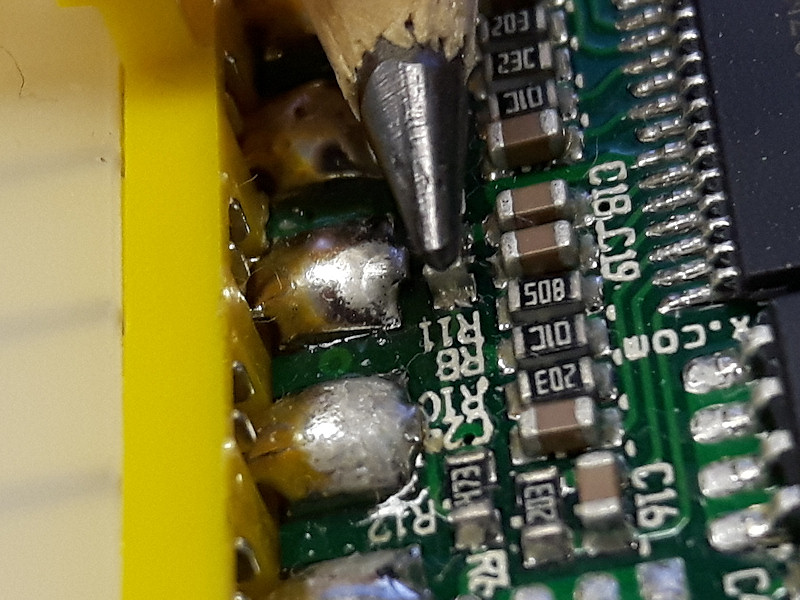
|
|
|
|
03 January 2017, 22:37
|
#13 |
|
Registered User
Join Date: Jan 2008
Location: United Kingdom
Age: 46
Posts: 733
|
Hi,
Nice fix. Does your converter have the same Texas Instruments, LM2642 device? Would it have been easier to chop down the Amiga power lead? The Amiga power lead uses 14 AWG cable, which at 2M long and 3A should drop 0.15V, as Demolition stated. Halving the cable length is another way to reduce the voltage drop. You can see why modern ATX supplies have short cables, supplying medium/high currents down a long cable makes it difficult to regulate the voltage without resorting to Kelvin sense (remote) connections. |
|
|
|
04 January 2017, 06:52
|
#14 |
|
Registered User
Join Date: May 2010
Location: Helsinki, Finland
Posts: 1,341
|
@Stedy
Yes, it's the LM2642. I did consider chopping down the cable, but it's got a nice molded plug on one end, and a bend protector at the other end so it would not be easy to do in a clean way. Also, I do want a decent length of cable so that I can put the enclosure on the floor or elsewhere out of sight. I measured the overall resistance on the 5V cable to be 0.11 Ω, although I can't say what portion of that is due to the connector and what is the wire itself. But certainly cutting down the length to something like 30 cm would make a considerable difference and is an option in some situations. This is how I have it set up (plus the 12V power brick on the floor): 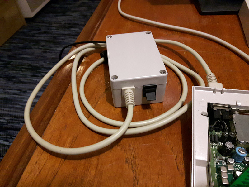
|
|
|
|
09 January 2017, 11:46
|
#15 |
|
Registered User
Join Date: Jun 2013
Location: Australia
Posts: 685
|
Having looked at the LM2642 data sheet, I think you’ve unintentionally sold me on the PSU
 Current limiting as well. I imagine you could do the voltage sense inside the PSU since the cable is never going to change. Is there a reason otherwise? I don’t expect too much change in resistance of the same cable over normal use of the computer, but of course, that’s conjecture. |
|
|
|
09 January 2017, 12:29
|
#16 |
|
Registered User
Join Date: Jun 2009
Location: Dublin, then Glasgow
Posts: 6,369
|
You can also get resistance introduced at the PSU connection on the mainboard which can contribute some voltage drop that would be impossible to detect from the PSU end. Of course cleaning the contacts will minimise this, but how many people have done that on their Amigas?
|
|
|
|
09 January 2017, 14:55
|
#17 |
|
Registered User
Join Date: May 2010
Location: Helsinki, Finland
Posts: 1,341
|
@xArtx
I think for now the simple resistor change is enough for my purposes. I just wanted something small I can use when testing out a system or bare motherboard In my experience, problems only really start when using something like a BlizzardPPC (which draws over 4 amps even when idle). The motherboard really isn't designed do power such a setup, and you need to start feeding power directly onto the accelerator, or at least the floppy connector which is nearby. This naturally bypasses the cable, connector and motherboard power plane and whatever resistance they introduce. |
|
|
|
09 January 2017, 15:12
|
#18 |
|
Registered User
Join Date: Jun 2013
Location: Australia
Posts: 685
|
It's only today that my Amiga current draw will exceed the stock PSU,
and can't really put it off anymore. Its a shame because the stock PSU still measures fine. High current supplies worry me with no fuses in the Amiga, unless you were going to do that yourself, but potentially current limiting the PSU if the stock part can already do it is a nice idea as well. |
|
|
| Currently Active Users Viewing This Thread: 1 (0 members and 1 guests) | |
| Thread Tools | |
 Similar Threads
|
||||
| Thread | Thread Starter | Forum | Replies | Last Post |
| Using a picoPSU: tired of the problems. Please help. | Amiga1992 | Hardware mods | 103 | 13 May 2017 05:52 |
| Adaptor for picoPSU | Solo761 | support.Hardware | 18 | 19 May 2014 15:02 |
| Amiga ruined picoPSU? | Amiga1992 | support.Hardware | 31 | 05 January 2014 02:54 |
| PicoPSU for Amiga | demolition | Hardware mods | 3 | 07 August 2013 16:05 |
| DESPERATE! Help with PicoPSU :( | Amiga1992 | Hardware mods | 40 | 14 November 2008 09:13 |
|
|


