
|
 18 March 2009, 14:52
|
#1 |
|
Registered User
Join Date: Feb 2009
Location: Glasgow, Scotland
Age: 44
Posts: 637
|
Joystick surgery... Microswitches fun
Got a second QS II Turbo Joystick this morning, since my first was a rather nasty Sigma Replica effort. The stick itself is in good nick, and feels nice and tight (ahem) . On testing, it would appear to work fine except for the top fire button. Being an inquisitive soul, I split the joystick and had a look.
First thing I noticed was that the top Microswitch lacked a spring, which obviously was causing things not to work. Fine, so I thought I'd cannibalise the spring off the other stick. Duly done, I got everything back together, and was rewarded with a satisfying *clicky clicky* noise from the top button. However, in games the top trigger still didn't work. So, I took it apart again and discovered that there was a wire loose. I am now at the stage where I'm about to take a trip to maplins and replace the two trigger microswitches. However I'm not sure how to wire things all up again when I get back (yes I know I have a soldering Iron) Looking at the stick, 3 wires come up from the base. Black and orange go to the front trigger. and a Red goes to the top button. There appears to be another short red wire (which was connected to one of the microswitches) but has come off completely. I'm guessing this was to connect the two switches together ? The good thing I suppose is that the top microswich has come loose (or was never connected) so I can take that with me when I go to maplins. Yes it seems a lot of hassle but I like the stick  . Pics will be posted when I recharge my phone.... . Pics will be posted when I recharge my phone....Andrew |

|
|
18 March 2009, 19:07
|
#2 |
|
Registered User
Join Date: Feb 2009
Location: Glasgow, Scotland
Age: 44
Posts: 637
|
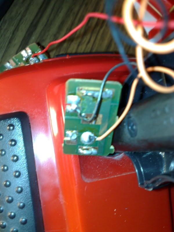
 Ok Red wire from base gone up to top switch. Now I'm left with this beasty:  Not sure where this lives but suspect it connects the two switches but where/how? Joystick works fine, just one button still. Ideas ? Andrew |
|
|
|
18 March 2009, 20:17
|
#3 |
|
Registered User
Join Date: Jan 2009
Location: Cornwall, England
Age: 34
Posts: 84
|
No experience with these sticks specifically but I'd say that wire you lost must be to connect that microswitch's ground wire to the other's ground/common wire. Why they used red I don't know, black or white are the typical ones. You can probably see the solder where the wire broke off on both ends, just solder it back on
ADD: And if not, some Hi-res pics of the solder side of the switches would help us get you on track |
|
|
|
18 March 2009, 21:00
|
#4 |
|
Registered User
Join Date: Feb 2009
Location: Glasgow, Scotland
Age: 44
Posts: 637
|
  I'm a novice with a soldering iron but the browning was done before I started. if the switch is knackered I can cannibalize the other stick. Last edited by asm1; 18 March 2009 at 21:02. Reason: pix duplicate - fixed |
|
|
|
18 March 2009, 21:05
|
#5 |
|
Registered User
Join Date: Sep 2005
Location: taunton.som.uk
Age: 73
Posts: 681
|
a bit fuzzy best i do for you
Last edited by twizzle; 18 April 2009 at 22:03. |
|
|
|
18 March 2009, 21:13
|
#6 |
|
Registered User
Join Date: Feb 2009
Location: Glasgow, Scotland
Age: 44
Posts: 637
|
Hmm so basically the bottom of the top switch (i.e. my second pic) goes to the front of the trigger switch ?
|
|
|
|
18 March 2009, 23:22
|
#7 |
|
Registered User
Join Date: Feb 2009
Location: Glasgow, Scotland
Age: 44
Posts: 637
|
It would appear my soldering skills arent up to it
 cant keep hands steady enough and am at risk of knackering it entirely / or myself.... cant keep hands steady enough and am at risk of knackering it entirely / or myself....Will have another look in the morning.... bleh |
|
|
|
19 March 2009, 00:42
|
#8 |
|
1 Potato to Spam´em all!
Join Date: May 2008
Location: Lost in a Wine Country
Age: 48
Posts: 572
|
For starters, just use something to keep the microswitch pcb in place while you sold the wire/s. Double sided duct tape, or even a little bit of hot glue will do just fine. Your hands will also stop shaking if your arms are well rested on the table top.
On the female plug DB9 pinout: 54321 top pins 9876 bottom pins 1- (usually red) Forward 2- (u.orange) Backward 3- (u.green) Left 4- (u.yellow) Right 5- (u.black) n/a 6- (u.blue) Fire A (trigger) 7- (u.brown) +5volts 8- (u.gray) Ground (all directions and fire buttons work when shorted with this one) 9- (u.white) Fire B (top button) The colors may vary but the pinout is always the same. If your not sure, use a test lamp or a multimeter first to test it before you solder. |
|
|
|
21 March 2009, 04:32
|
#9 |
|
Precious & fragile things
Join Date: Feb 2009
Location: Victoria, Australia
Posts: 1,946
|
Greetings,
Switches would have to be in parallel, so all firing switches would be wired as such; Code:
fire  -----+-------------+---------------+
           S1           S2              S3
common-----+-------------+---------------+
Paul Last edited by Loedown; 22 March 2009 at 00:26. |
|
|
|
21 March 2009, 17:00
|
#10 |
|
Global Moderator
Join Date: Aug 2008
Location: Sidcup, England
Posts: 10,300
|
Hi Loedown,
If you put <code> and </code> tags at the start and end, respectively, of your wiring diagram, then it will look OK when submitted.  prowler PS. Use square brackets for the tags, not arrowed ones. 
|
|
|
|
22 March 2009, 00:27
|
#11 |
|
Precious & fragile things
Join Date: Feb 2009
Location: Victoria, Australia
Posts: 1,946
|
Greetings,
Thanks Prowler, now it looks almost correct. First they made me learn HTML, then damned CSS, <sigh> Paul |
|
|
| Currently Active Users Viewing This Thread: 1 (0 members and 1 guests) | |
| Thread Tools | |
 Similar Threads
|
||||
| Thread | Thread Starter | Forum | Replies | Last Post |
| Quickshot Python: crap joystick or crappest joystick ever? | T_hairy_bootson | Nostalgia & memories | 141 | 13 September 2016 15:36 |
| Amiga 500 Plus Surgery | Reptile | Hardware pics | 8 | 18 December 2010 14:02 |
| Wanted: Commodore mouse microswitches | Magno Boots | MarketPlace | 6 | 15 March 2008 08:43 |
| Replacement Microswitches? | Dastardly | support.Hardware | 2 | 11 June 2005 12:15 |
| amiga open-heart surgery | rattus | support.Hardware | 12 | 01 March 2003 10:57 |
|
|


