
|
 02 September 2019, 11:19
|
#41 | |
|
Registered User
Join Date: Aug 2014
Location: Netherlands
Posts: 695
|
Quote:
|
|

|
|
04 September 2019, 02:31
|
#42 |
|
Registered User
Join Date: Aug 2017
Location: Southfield
Posts: 53
|
Hi Kai. Could you please add this 8mb board to PCBWay Please, and make the jed files available too..
Thanks.. EDIT: What's the value of the caps C11, C12 are they 0.1Uf.. Same as the other ten... Not this board but the through-hole one.. Last edited by hooleydog; 08 September 2019 at 05:07. |
|
|
|
15 September 2019, 14:41
|
#43 |
|
Registered User
Join Date: Apr 2011
Location: Brighton, UK
Age: 41
Posts: 114
|
I wont add the board to PCBWay just yet - thats why everything is hosted on github - you can upload the gerbers in a .zip and have a batch made - i've not fully tested the AIO - it's will a WiP project.
|
|
|
|
19 September 2019, 04:28
|
#44 | |
|
Registered User
Join Date: Aug 2017
Location: Southfield
Posts: 53
|
Quote:
OK No problem |
|
|
|
|
04 November 2019, 19:34
|
#45 | |
|
Registered User
Join Date: Aug 2014
Location: Netherlands
Posts: 695
|
Quote:
A500ide_PCB.zip |
|
|
|
|
04 November 2019, 20:36
|
#46 |
|
Registered User
Join Date: Jul 2017
Location: Germany
Posts: 205
|
I can't open it in kicad. Can't upload pictures anymore. Error loading boardfile, can't copy info out of the window.
Last edited by katarakt; 04 November 2019 at 20:42. |
|
|
|
04 November 2019, 20:40
|
#47 | |
|
Registered User
Join Date: Aug 2014
Location: Netherlands
Posts: 695
|
Quote:
I just tried in 4.0.7 and it works fine! |
|
|
|
|
04 November 2019, 20:43
|
#48 |
|
Registered User
Join Date: Jul 2017
Location: Germany
Posts: 205
|
Have editd my post.
Application: KiCad Version: (5.1.4)-1, release build Libraries: wxWidgets 3.0.4 libcurl/7.61.1 OpenSSL/1.1.1 (WinSSL) zlib/1.2.11 brotli/1.0.6 libidn2/2.0.5 libpsl/0.20.2 (+libidn2/2.0.5) nghttp2/1.34.0 Platform: Windows 8 (build 9200), 64-bit edition, 64 bit, Little endian, wxMSW Build Info: wxWidgets: 3.0.4 (wchar_t,wx containers,compatible with 2.8) Boost: 1.68.0 OpenCASCADE Community Edition: 6.9.1 Curl: 7.61.1 Compiler: GCC 8.2.0 with C++ ABI 1013 Build settings: USE_WX_GRAPHICS_CONTEXT=OFF USE_WX_OVERLAY=OFF KICAD_SCRIPTING=ON KICAD_SCRIPTING_MODULES=ON KICAD_SCRIPTING_PYTHON3=OFF KICAD_SCRIPTING_WXPYTHON=ON KICAD_SCRIPTING_WXPYTHON_PHOENIX=OFF KICAD_SCRIPTING_ACTION_MENU=ON BUILD_GITHUB_PLUGIN=ON KICAD_USE_OCE=ON KICAD_USE_OCC=OFF KICAD_SPICE=ON |
|
|
|
04 November 2019, 20:44
|
#49 |
|
Registered User
Join Date: Jul 2017
Location: Germany
Posts: 205
|
Sure problem is the old version vs new version. Kicad is very bad when it comes to compatibility.
|
|
|
|
02 January 2020, 19:45
|
#50 |
|
Registered User
Join Date: Jan 2020
Location: Budapest
Posts: 5
|
Can anyone confirm that this is a working circuit? I mean, specifically this version: Link
I built one but unfortunately not working. I replaced every ICs at least three time but no succes. Then I started analyzed the circuit. I found a interesting thing: The SW_E14 line only connect to Input pins: U6 pin1, U8 pin2, U7 pin5. U6 pin1 is a JK flip-flop clock input. U8 pin2 is a multiplexer input. And U7 pin5 is a inverter input. So... what is drive the SW_E14 line? Because I only see inputs. |
|
|
|
03 January 2020, 02:39
|
#51 | |
|
Registered User
Join Date: Feb 2014
Location: Maitland / AUSTRALIA
Posts: 205
|
Quote:
Im in the same boat as you. I had 5 boards made, I've assembled one and it didn't work. I've replaced all the chips and still nothing. I was assembling another one last night (without IC sockets this time) but my soldering iron died before I could complete it. So I suspect it wont work either after your comment. Unfortunately my skill level wont let me help diagnose the problem. I can read basic schematics, but the one in the file was impossible for me to understand. I did find a more conventional schematic from what this one is based, if thats of use? If you get somewhere with it I would be interested. Ash |
|
|
|
|
03 January 2020, 13:27
|
#52 | |
|
Registered User
Join Date: Jan 2020
Location: Budapest
Posts: 5
|
Quote:
I found another error on sheet 2. The U8 IC (74LS157) PIN4 is a output (E_OUT). This signal goes to sheet 1. On sheet 1 this signal is renamed CPU_E14 and this is connect to U2 (68HC000) PIN 22. The problem is: This PIN 22 is a output on CPU side. So we connect two output together. Which is a very bad idea. I think this circuit was never built or tested by the designer. |
|
|
|
|
04 January 2020, 08:58
|
#53 | |
|
Registered User
Join Date: Aug 2014
Location: Netherlands
Posts: 695
|
Quote:
 . .First we need to know how it works. As far as I can tell: The JK flipflip connecting to SW_E14 / E_OUT is to divide the E clock by two. Otherwise the E clock will run too fast. Furthermore there is some scary stuff around U3 (RC delays  ) to get a 14MHz clock in the right phase. I wonder how well this part runs. ) to get a 14MHz clock in the right phase. I wonder how well this part runs.The rest of the stuff is for AS/DTACK and VMA/VPA arbitration. To get this to run will require some evenings wiith a scope and logic analyzer. And, imho, some rework of the power supply decoupling. |
|
|
|
|
04 January 2020, 10:48
|
#54 |
|
Registered User
Join Date: Jan 2020
Location: Budapest
Posts: 5
|
I already found a another version.
I guess that was the "source" for this project. The PCB layout was only 3 jpg image but I did some PS magics to overlay the images. So here is it the combined version. This should be enough to redraw the circuit. 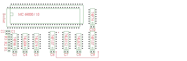 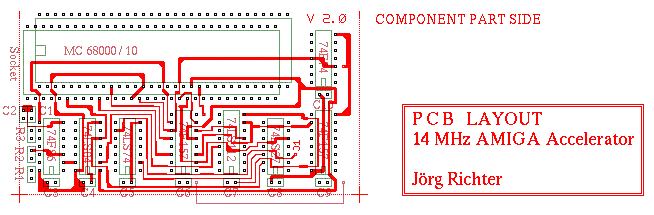 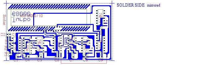 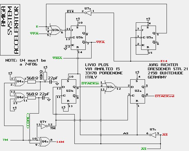
|
|
|
|
04 January 2020, 17:30
|
#55 |
|
Registered User
Join Date: Jan 2020
Location: Budapest
Posts: 5
|
So... I played with a clock doubler circuit a little bit. And obvious the 74HCT86 is too slow to generate a stable 14 Mhz clock.
Here is the 14Mhz waveform with two different 74HCT86 IC: First one: 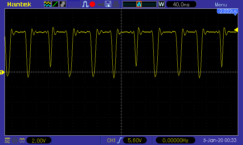 Second one: 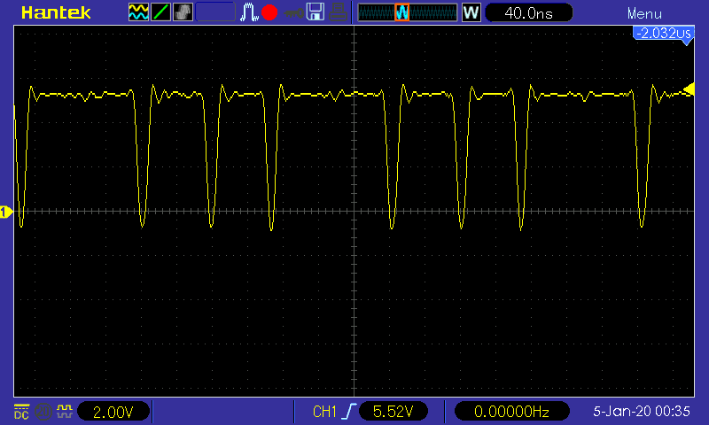 First one is almost good, but the 4th pulse is too short. The second one is just too slow to generate the 4th pulse. Time to buy a few 74F86... |
|
|
|
04 January 2020, 21:49
|
#56 | |
|
Registered User
Join Date: Aug 2014
Location: Netherlands
Posts: 695
|
Quote:
The problem is that the rc delay is too long. On U4C on above schematic two versions of the 7MHz clock are put in, the original one and one delayed by about 35 nano seconds. The 35 nano second is achieved by the two rc delay circuits. Try reducing the delay by making the two 22pf caps a bit smaller (15pf or 10pf). The aim is to get a nice 50% dutycycle 14MHz clock. Last edited by Mathesar; 05 January 2020 at 06:40. |
|
|
|
|
05 January 2020, 01:25
|
#57 |
|
Retro maniac
Join Date: Feb 2017
Location: near Munich / Germany
Posts: 485
|
Choose AHCT if HCT is too slow..
|
|
|
|
05 January 2020, 09:53
|
#58 |
|
Registered User
Join Date: Oct 2017
Location: Germany
Posts: 193
|
For debugging purposes, simply feed CDAC and 7mhz into U4c and disconnect U4d output into U4c. This will then generated a synchronised 14mhz clock with solid edges. I think the original circuit had this as an option (green text).
|
|
|
|
12 January 2020, 08:55
|
#59 |
|
Registered User
Join Date: Aug 2014
Location: Netherlands
Posts: 695
|
Any progress?
|
|
|
|
12 January 2020, 12:30
|
#60 |
|
Registered User
Join Date: Jan 2020
Location: Budapest
Posts: 5
|
This circuit has too many problems... I fixed the obvious errors, but it still doesn't work.
I need to find a working one so I can compare the signals with oscilloscope.  
|
|
|
| Currently Active Users Viewing This Thread: 1 (0 members and 1 guests) | |
| Thread Tools | |
 Similar Threads
|
||||
| Thread | Thread Starter | Forum | Replies | Last Post |
| DMA debugger and 14Mhz 68K | ovale | support.WinUAE | 3 | 10 June 2014 15:10 |
| AGA on 14mhz 68000 | little | request.UAE Wishlist | 6 | 03 May 2012 23:09 |
| A2620 Accelerator Card 12mhz instead of 14mhz. Problem? | kjmann14 | support.Hardware | 1 | 19 May 2011 00:35 |
| A500 MTEC 68030/14Mhz | bebek | Hardware mods | 9 | 20 January 2010 22:30 |
|
|


