
|
 22 May 2016, 06:17
|
#1 |
|
Registered User
Join Date: Jun 2013
Location: Australia
Posts: 685
|
CD32 CD Error Rate Counter PCBs (Pic Heavy)
Hi Guys
 I thought I’d share my findings of the CD32 Error Rate Counter boards used for testing Amiga CD32 units at West Chester production, and maybe update as I go. CD Error Rate Counter boards:  I purchased the two boards individually from eBay toward the beginning of the year. I’ve only powered them to check nothing warmed up, and all was ok. They have a 7805 regulator, and were probably powered from a 12 Volt bench supply. From there, investigation of the 26 pin header connector suggested strongly that it’s actually a 25 pin parallel port connected to the test station computer. When a cable was made to connect a 26 way IDC header connector to a ribbon 25 way D connector with pin 1 aligned with the connector at each end, all pins aligned for a parallel port with all grounds connected and common to each other, data bus D0-D8 all connected, and also control pins for BUSY and Select are connected. The 26th pin of the header connector is not connected to anything on the PCB, and is simply cut off as it doesn’t fit in a 25 way D ribbon connector. Commodore probably just pulled the 26th wire off the ribbon cable completely. 25 pin D Parallel cable: 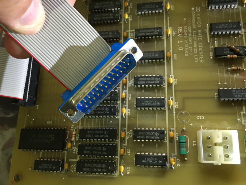 25 pin PC/Amiga Parallel Port (for reference) : https://upload.wikimedia.org/wikiped...inouts.svg.png Over to the input header connector, it looks to connect the error status monitor output of the Sony CXD2500BQ controller chip on the CD drive controller board. The MNTR test points can be seen toward the top right of the CD controller board. The CD drive unit is Chinon brand, but uses several Sony chips. Chinon CD Drive Controller Board (Amiga CD32) : 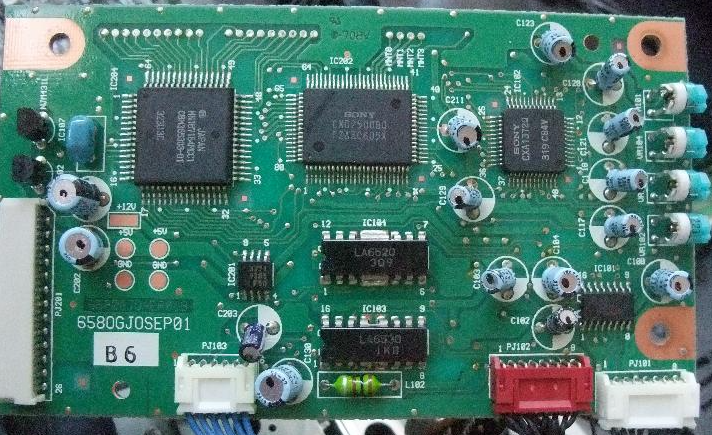 Investigation of the data sheet for Sony CXD2500BQ suggests manufacturers connect some equipment to this 4 bit port to monitor error status output. The text also seems to suggest that the value of all 1s (decimal 7) on the 4 bit port is the only uncorrectable error, as a failed C1 correction is passed on to C2 error correction, and if that fails, the error is uncorrectable. Sony CXD2500BQ (CD Drive Controller) Monitor output Error Correction Table: 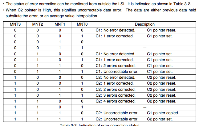 It occurs to me quite possible that the error counter boards logical AND all four bits of the port together, only looking for the value b1111, and count that. Though I haven’t looked too hard at the logic on the board yet, it only has three pulse extender hardware chips, which seems consistent with use of this port, as the bit MNTR3 is always at least twice as long as the other three bits. The RFCLK line referenced on the timing chart may not be on the same test port, but is available on a Sony CXD2500BQ chip if it is needed for the port timing. It could be the lone test point off to the right a little from the MNTR port. Pin 5 of the 5 pin input port to the Error Counter board is Ground, so I don’ think it is used at all, lending to the theory that the 4 bits are logical ANDed. Sony CXD2500BQ Monitor Bus Timing: 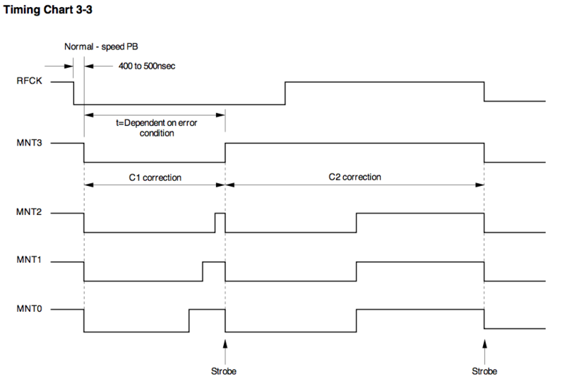 Now I think the counter data is encoded for the 8 bit parallel port output, and the BUSY and Select pins used perhaps for latching and resetting the counters on the PCBs. Probably the case that’s it’s simply a frequency counter, but yet to be determined. It seems fitting to write the software for an Amiga, but to get it done faster, sticking with what I know, it would probably be smoother for me to get it done with a dedicated microcontroller board, and maybe over to an Amiga from there. Cheers, Art. Last edited by xArtx; 22 May 2016 at 06:34. |

|
|
03 June 2016, 20:27
|
#2 |
|
Registered User
Join Date: Jun 2013
Location: Australia
Posts: 685
|
I got the thing working tonight
The error output from the CD32 CD drive is being simulated by the same microcontroller that’s also reading the parallel port input back from the error counter PCB. One of the control pins on the parallel port that would have been controlled by the test station computer enables counting, and the other is probably the counter reset. So far I’m just letting the counter overflow, and it begins from zero again. The LED bargraph displays the eight bit output of the parallel port (from the counter PCB), and the 4x 10mm LEDs indicate the simulated 4 bit CD drive error output that would normally come from Sony CDX2500BQ CD drive interface chip (currently from the test PCB). The real power connector for the board I got as a free sample from TE Connectivity  Video of testing: [ Show youtube player ] 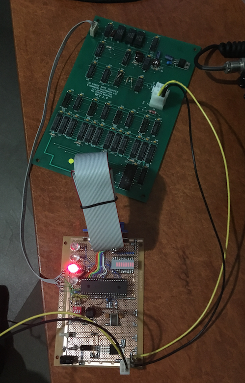
Last edited by xArtx; 06 June 2016 at 10:45. |
|
|
| Currently Active Users Viewing This Thread: 1 (0 members and 1 guests) | |
| Thread Tools | |
 Similar Threads
|
||||
| Thread | Thread Starter | Forum | Replies | Last Post |
| Address pointers with Program Counter | Lonewolf10 | Coders. Asm / Hardware | 8 | 27 October 2015 11:40 |
| Program Counter with Offset - why? | Jherek Carnelia | Coders. General | 26 | 21 March 2011 10:49 |
| High quality pic of CD32 Pad | Bigby | request.Other | 2 | 07 January 2010 16:23 |
| If the Amiga custom chips were real people... (may get pic heavy, not 56k!) | Paul_s | Amiga scene | 7 | 12 October 2007 22:53 |
|
|


