
|
 31 January 2011, 21:05
|
#101 | |
|
Registered User
Join Date: Sep 2009
Location: Aarhus
Posts: 32
|
Quote:
http://cgi.ebay.co.uk/ws/eBayISAPI.d...m=230565289473 |
|

|
|
31 January 2011, 21:42
|
#102 |
|
Registered User
Join Date: Apr 2010
Location: Scotland
Posts: 523
|
Hi, This thread is just is just amazing
 Ultimate A1200 One can only dream of. Ultimate A1200 One can only dream of.  Hopefully one day I shall have one two Hopefully one day I shall have one two  
|
|
|
|
04 February 2011, 14:56
|
#103 | |||
|
WipEout Fanboi
Join Date: Apr 2010
Location: Ringsted / Denmark
Age: 48
Posts: 263
|
Quote:
 Quote:
|
|||
|
|
|
04 February 2011, 14:57
|
#104 | |
|
WipEout Fanboi
Join Date: Apr 2010
Location: Ringsted / Denmark
Age: 48
Posts: 263
|
Quote:
|
|
|
|
|
05 February 2011, 19:56
|
#105 |
|
WipEout Fanboi
Join Date: Apr 2010
Location: Ringsted / Denmark
Age: 48
Posts: 263
|
Here's a few more bits and bobs i've been up to with this mad beast: -
I put some more space between the USB ports: - 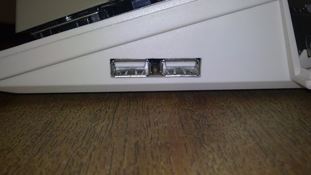 I made the Delfina output ports a little neater: -  Here it is in the system: -  It fits in quite nicely! And now here is the startings of my home made Auto Video Switcher: -  Its an LT1675 specially made for such switching. It takes in the RGB signals from both sources (Indivision and BVision) and with either a logic 0 or 1 on pin 10 it switches the inputs. This ties in with a CD4053 controlling the H and V sync signals. this IC runs in +5V and -5V so the CD4053 has to be powered likewise to match. I have to go under the scope to solder this little beaut: - 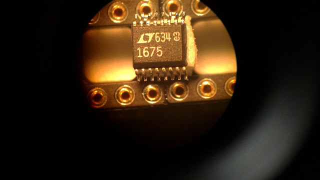 These are the wires I chose to solder to the Chip, some old 80 way IDE cable, i've stripped them carefully and tinned them: -  They line up well: -  And now soldered on, this took some doing actually! Almost as hard as my BV repair! : -  Now its ready to have the small wires soldered to the socket: -  Done! : -  Now I needed to weigh up where the Indi and BV plug in. Heres the Indi wire now cut from its VGA cable and I replaced it with a 10 pin IDC. I chose Grey: - 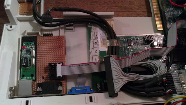 To make sure I had a way to check the signals directly, I soldered the old VGA plug to a 10 pin socket: -  This will be used for checking the signals many times whilst testing my CCT:-  Here I have made a completely new cable for the BV, I chose black for its plug and also inverted the socket so that there is no way I can get the two mixed up. The pinouts for the BV and Indi ARE different. Same plug doesn't mean same pin layout.  If anyone is interested here are the pinouts for the Indivision to VGA: - Ribbon - VGA Plug 1 - > 1 (Red) 2 - > 6 (Red GND) 3 - > 2 (Green) 4 - > 7 (Green GND) 5 - > 3 (Blue) 6 - > 8 (Blue GND) 7 - > 5 (GND) 8 - > 13 (H Sync) 9 - > 14 (V Sync) 10 - > 4 (Monitor ID) And the pinout for BV : - Ribbon - VGA Plug 1 - > 1 (Red) 2 - > 6,7,8 (all GND) 3 - > 2 (Green) 4 - > 6,7,8 (all GND) 5 - > 3 (Blue) 6 - > N/C (Don't connect this pin) 7 - > 13 (H Sync) 8 - > N/C (Don't connect this pin) 9 - > 14 (V Sync) 10 - > 5, 10 (GND, connected with 6,7,8 ) Ok, on with the show, here's what the floppy drive looks like over the cables, I made an intentional kink in the BV wire so its not resting on the Heatsink: - 
|
|
|
|
05 February 2011, 19:56
|
#106 |
|
WipEout Fanboi
Join Date: Apr 2010
Location: Ringsted / Denmark
Age: 48
Posts: 263
|
Angle shot: -
 And here is the AVS all wired up and finished!  It takes +5V in and this is inverted with a DC converter, this is fed to the CD and the LT. The Transistor is used to switch the signal logic from pin 13 of the parallel port all the signals are tied to 75 ohm resistors, but the output from the LT has 33 ohm in series to bring the amplification down (otherwise the screen is too bright): -  Side view to see the labelling on the ports.. just incase   Here is the underneath, it turned out a little messy, but its ok, it all fits in nice. I soldered ground lines directly to the board, then wired everything else over these: -  Sat in its new home: -  Closer look, can you see that grey wire trailing off the left?...  It goes here (Pin 13 of the parallel port): -  A wide shot just to see how mental this 1200 has become! :-  And now some you tube vids to see it in action, does it work? Oh yes  : - : -[ Show youtube player ] [ Show youtube player ] Excuse the darkness, the light fitting over the table has gone duff (I have to fix it tomorrow along with the wifes bike, sunday jobs, boo hiss) All the info I used to make this AVS is available here: - http://mitglied.multimania.de/camiga/index_e.html I also want to thank Christian personally for his awesome help whilst making this, cheers! so whats to come? Well I got some of these :-  So will soon have my own 3.9 ROMs  And I also want to make an audio mixer, Get a decent monitor, and a few other last bits and bobs before I try and start from scratch with WB 3.1... Thanks for looking! 
|
|
|
|
05 February 2011, 20:03
|
#107 |
|
Professional slacker!
Join Date: Jul 2009
Location: Kent, UK
Age: 44
Posts: 6,685
 |
I'm sure someone else has done this already, a guy over at Amibay.
Oh wait - It was you Your l33t SkillZ still Roxors my friend Steve. 
|
|
|
|
05 February 2011, 20:04
|
#108 |
|
Paranoid Amigoid
Join Date: Mar 2008
Location: Athens/Greece
Age: 45
Posts: 1,978
 |
Not much can be said about this Legendary hack/mod/homebrew awesomeness!
Les this was indeed and orgasmic pr0n evening You rock! |
|
|
|
05 February 2011, 20:28
|
#109 |
|
Registered User
Join Date: Apr 2010
Location: Scotland
Posts: 523
|
Great Stuff love the under the scope photos, a bit like key hole surgery, Dr Phipscube

|
|
|
|
05 February 2011, 20:34
|
#110 | |
|
WipEout Fanboi
Join Date: Apr 2010
Location: Ringsted / Denmark
Age: 48
Posts: 263
|
Thats not me! its my Doppelganger! And he always JUST pips me to the post over on Amibay! It gets me SOOO MAAAD!
 Quote:
Last edited by TCD; 05 February 2011 at 20:44. Reason: Back to back posts merged. Use the edit function. |
|
|
|
|
05 February 2011, 21:40
|
#111 |
|
Ruler of the Universe
Join Date: Mar 2010
Location: Lanzarote/Spain
Posts: 6,195
|
I have no dude: IMHO this is the greatest mod in an A1200. Congratulations!
|
|
|
|
07 February 2011, 13:43
|
#112 | |
|
WipEout Fanboi
Join Date: Apr 2010
Location: Ringsted / Denmark
Age: 48
Posts: 263
|
Quote:
|
|
|
|
|
07 February 2011, 14:31
|
#113 |
|
Registered User
Join Date: Sep 2009
Location: Norway
Posts: 1,715
|
No doubt the best A1200 mod ever published on the Internet. Everything here is sophisticated and professional looking, and the way you use the tiny space in the chassis is fascinating. I give this a 1000 out of 10 stars.
|
|
|
|
10 February 2011, 20:53
|
#114 |
|
WipEout Fanboi
Join Date: Apr 2010
Location: Ringsted / Denmark
Age: 48
Posts: 263
|
Here's a few more little things i've been hacking away at: -
My clock port expander had been bugging me a little, I don't like the way it sits so rigidly, the slightest movement and it causes issues with the Subway and Delfina (probably more to do with the riser). I also wanted to try and figure a way to get some heatsinks on my BV RAM so.... I took off the connector: -  And replaced it with some old clock port cable (its short on purpose as the expander has to be as close as possible to the clock port): -  Thats the old connector with the riser needed to run it with a BV installed sat next to it. So now I can plug the Expander in like this: -  I'll find some nice 5mm Heatsinks for themz RAM chips now I've also added a +5V lead onto my Delfina, Since putting the BV in its been a bit touchy now and then on a cold boot (it doesn't initialise) Also sometimes on a soft reset: -  Here's the Fly lead connected: -  The pin needs to connect to the "top right" pin, or as I have done, soldered to the right side of the capacitor. This little lead has made my Delfina work perfect now! I think it just couldn't get enough juice through that CP expander sometimes. Here's my mixer solution: -  Quite a simple affair really. Just has 10K ohm resistance on each of the left and right from native and delfina outputs, then both channels are connected together after the Pots. All grounds are linked together and run along the back ready to mount to the internal sheilding of the A1200 (I used pots so I can change the volume levels and balance them off so both outputs are at similar levels if not the same, the native amiga is a little higher than Delfina you see). Underneath: -  Going into the A1200 now, i've added some wire loops that I will solder to the chassis :-  Resting loosely in place so I can test all is ok. It sits nicely 
Last edited by phipscube; 10 February 2011 at 21:51. Reason: spelling errors |
|
|
|
10 February 2011, 20:54
|
#115 |
|
WipEout Fanboi
Join Date: Apr 2010
Location: Ringsted / Denmark
Age: 48
Posts: 263
|
And if you look closely you can see its soldered to the metal sheilding now: -
 It super solid, much better than my earlier hot glued cludge From the outside you'd never know any difference (well apart from that they are actually straighter than original, what is it with Commodore and its wonky phono plug placement!?) That's it for this session, I hope you like these rather small mods All the exciting stuff is done now so it will be "finishing off" from now as she is just about done.I'm going to add some 3.5 mm jacks to the sides near the USB ports (If I can squeeze them in) for mic and line input to delfina, I may add a +5V line to Subway also just incase. I'll also add heatsinks to all 8 RAM chips on the BV and two on certain hotties on the BPPC. I'm also strongly considering dropping the 060 to 50MHz. I've got a decent Laser thermometer now that "Scans" and its just getting too hot for my liking. Otherwise i'll have to give in and add 4 big fat stupid rubber bungs underneath the old girl (I really don't want to though). Another option is 2x 6mm fans directly on the PPC and 060 but thats just more juice. We'll see, i'm pondering all that right now. The last thing i'll do is the 3.9 ROMS (Once I know everything else is working fine) Cheers! 
|
|
|
|
10 February 2011, 23:22
|
#116 |
|
Ruler of the Universe
Join Date: Mar 2010
Location: Lanzarote/Spain
Posts: 6,195
|
So for the photos, do you only connect it to the right native output of the Amiga?
|
|
|
|
11 February 2011, 00:53
|
#117 |
|
Paranoid Amigoid
Join Date: Mar 2008
Location: Athens/Greece
Age: 45
Posts: 1,978
|
Stop being so full of win FFS!
Les bro I salute with respect. Epic implementation all the way!!! I so much want to make an Mixer for my own Delf but will see soon Thanks for sharing such elegant mods my friend. |
|
|
|
11 February 2011, 12:30
|
#118 | ||
|
WipEout Fanboi
Join Date: Apr 2010
Location: Ringsted / Denmark
Age: 48
Posts: 263
|
Quote:
Quote:
http://www.tkk.fi/Misc/Electronics/c...s/linesum.html And replaced the 10K ohm resistors with pots. Last edited by phipscube; 11 February 2011 at 12:36. Reason: extra info |
||
|
|
|
12 February 2011, 15:33
|
#119 |
|
The 1 who ribbits
Join Date: Apr 2006
Location: leek, Staffs, UK
Age: 56
Posts: 3,557
|
wibble er I mean Ribbits heheheh very nice, watch out you don`t give fitz too many great ideas ..... LOL
|
|
|
|
14 February 2011, 09:30
|
#120 | |
|
WipEout Fanboi
Join Date: Apr 2010
Location: Ringsted / Denmark
Age: 48
Posts: 263
|
Quote:
I think its too late for Mr Fitz now, he's already taken the plunge with a soldering iron.. no looking back now! I'm looking forward to seeing what he gets up to
|
|
|
|
| Currently Active Users Viewing This Thread: 1 (0 members and 1 guests) | |
| Thread Tools | |
 Similar Threads
|
||||
| Thread | Thread Starter | Forum | Replies | Last Post |
| A1200D BPPC Project | Retrofan | Hardware mods | 107 | 01 October 2015 12:46 |
| A1200D Project - Mechanical Compat. Advice | rikbliz | support.Hardware | 33 | 22 August 2012 13:58 |
| My custom A1200D PPC :) | mfilos | Hardware mods | 105 | 15 January 2012 12:04 |
| My A1200D =) | fitzsteve | Hardware pics | 33 | 03 October 2010 14:41 |
| PicoPSU 120W internal in A1200D | keropi | Hardware mods | 102 | 05 August 2008 07:49 |
|
|


