
|
 21 September 2014, 13:38
|
#41 | |
|
Registered User
Join Date: Jul 2014
Location: Cheshire
Posts: 66
|
Quote:
|
|

|
|
21 September 2014, 15:56
|
#42 | |
|
Registered User
Join Date: May 2006
Location: Kilmacolm
Age: 46
Posts: 632
|
Quote:

|
|
|
|
|
22 September 2014, 13:03
|
#43 |
|
Registered User
Join Date: Jul 2014
Location: Cheshire
Posts: 66
|
ok thanks, I'll try this during the week and let you know.
|
|
|
|
25 September 2014, 09:57
|
#44 |
|
Registered User
Join Date: Dec 2009
Location: poland
Posts: 307
|
thanks kipper, life saving tutorial for my A600
|
|
|
|
25 September 2014, 14:08
|
#45 |
|
Registered User
Join Date: Jul 2014
Location: Cheshire
Posts: 66
|
The 74HCT244 arrived this morning. There's nothing that I can see to indicate which side pin 1 is on the original or the new one. I guess I should orientate it with the screen printed information in the same direction as the original one although that's not guaranteed to be the same. There is a notch in both of the chips so I suppose that must be what indicates which way to orientate it.
|
|
|
|
25 September 2014, 16:07
|
#46 |
|
-
Join Date: Jul 2003
Location: Helsinki / Finland
Age: 43
Posts: 9,900
|
The notch is the only thing you should rely on, it is what indicates what end has pin 1.
|

|
|
25 September 2014, 16:10
|
#47 |
|
Registered User
Join Date: Jul 2014
Location: Cheshire
Posts: 66
|
Well I tried for an hour with flux and braid to remove the old one but it was stuck solid so I tried to cut the legs off instead and inevitably 4 of the pads have lifted off the board entirely when I eventually removed it
 I know that pads can be replaced but I think it's beyond me. I'm pretty gutted about it. I know that pads can be replaced but I think it's beyond me. I'm pretty gutted about it.
|
|
|
|
25 September 2014, 16:12
|
#48 | |
|
Registered User
Join Date: Jul 2014
Location: Cheshire
Posts: 66
|
Quote:
|
|
|
|
|
28 September 2014, 21:47
|
#49 | |
|
Registered User
Join Date: May 2006
Location: Kilmacolm
Age: 46
Posts: 632
|
Quote:
For future reference, solder braid is not a good way to remove chips. It can practically never remove all the solder from a pin, a little "sweat joint" is nearly always left behind, the suction of the braid being too little for the adhesive force of such a tiny area of solder. The pin remains stuck to the pad and if you keep reheating, the bond of the pad to the board is permanently weakened as you have found. I find braid is only really good for cleaning up after components are removed. Hot air is the usual way but for small SOIC like U31 you can remove it by adding a blob of solder to each side bridging all pins, then alternate heating one side then the other until both blobs stay molten for a moment allowing you to quickly remove the chip. |
|
|
|
|
28 September 2014, 23:01
|
#50 | ||
|
Registered User
Join Date: Jul 2014
Location: Cheshire
Posts: 66
|
Quote:
Quote:
|
||
|
|
|
28 September 2014, 23:14
|
#51 |
|
PSPUAE DEV
Join Date: Nov 2006
Location: Wales / UK
Age: 45
Posts: 6,039
  |
Got any pics of the damage.
If you dont use a rework station, you could use the heat one leg then lift with a fine screwdriver method. Its all about experience. The loop of wire method, we used to use that back in the day before my previous company bought a rework station (long overdue, the boss didn't want to spend over £1000, which was the cost back then). You should be able to get away with repairing the track with fine wire. I have used this method loads of times when someone has sent a board to us they have damaged. 90% of the time, you cant even see where it was damaged. |
|
|
|
29 September 2014, 00:31
|
#52 | ||
|
Registered User
Join Date: Jul 2014
Location: Cheshire
Posts: 66
|
Quote:
Quote:
|
||
|
|
|
29 September 2014, 00:34
|
#53 | |
|
PSPUAE DEV
Join Date: Nov 2006
Location: Wales / UK
Age: 45
Posts: 6,039
|
Quote:
I tend to look for decent anchoring points, sometimes the broken track goes to through hole contact. You can use that to solder to, you can normally push the wire through to make it secure. |
|
|
|
|
29 September 2014, 16:30
|
#54 |
|
Registered User
Join Date: Jul 2014
Location: Cheshire
Posts: 66
|
Here's the macro photo of U31. My old phone isn't the best, I couldn't get it to focus correctly but hopefully it's good enough to see what I've done.
Four of the pads came away and a couple of others have partially come away from the board. The traces look intact however. 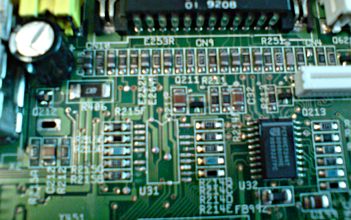
|
|
|
|
29 September 2014, 18:44
|
#55 | |
|
PSPUAE DEV
Join Date: Nov 2006
Location: Wales / UK
Age: 45
Posts: 6,039
|
Quote:
 . .Im trying desperately to zoom in. Quick look at schematics. You may be lucky and find the pads connected to nothing are broken. However Im not sure the schematic is correct, think they just copied the A1200. U31 is 20 pins, yet shows it as atleast 24 pins. Last edited by FOL; 29 September 2014 at 18:53. |
|
|
|
|
29 September 2014, 19:17
|
#56 |
|
Registered User
Join Date: Jul 2014
Location: Cheshire
Posts: 66
|
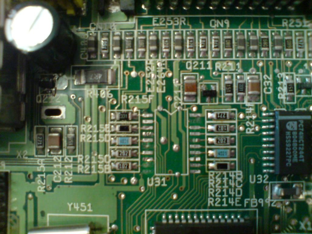
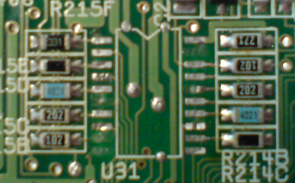
I've taken a further photo now which looks in better focus and is not scaled this time
|
|
|
|
29 September 2014, 19:29
|
#57 |
|
Registered User
Join Date: Jul 2014
Location: Cheshire
Posts: 66
|
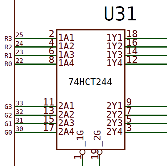
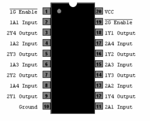
Here's U31 from the A600 schematics pdf and the 74HCT244 pin outs
|
|
|
|
29 September 2014, 22:12
|
#58 |
|
PSPUAE DEV
Join Date: Nov 2006
Location: Wales / UK
Age: 45
Posts: 6,039
|
EDIT:- strach that, looking at wrong bloody manual,
.I can see from your pics, where the pads are supposed to go. Best to scrap a little bit to expose copper, then beap out each borken track to where they should go. Then use wires from that point to the leg of IC. Last edited by FOL; 29 September 2014 at 22:28. |
|
|
|
29 September 2014, 22:21
|
#59 |
|
Registered User
Join Date: Jul 2014
Location: Cheshire
Posts: 66
|
The schematics I'm working from is A600_R2.pdf that was linked in another thread here on eab.
Do you think doing a proper repair with the circuit frame kit would be easier? |
|
|
|
29 September 2014, 22:28
|
#60 | |
|
Registered User
Join Date: Jul 2014
Location: Cheshire
Posts: 66
|
Quote:
EDIT: lol I've just seen your edit, never mind
|
|
|
|
| Currently Active Users Viewing This Thread: 1 (0 members and 1 guests) | |
| Thread Tools | |
 Similar Threads
|
||||
| Thread | Thread Starter | Forum | Replies | Last Post |
| Specification for A1200 Caps Lock LED? | rikbliz | support.Hardware | 7 | 20 January 2013 00:59 |
| Caps Lock issues under Wine | mark_k | support.WinUAE | 11 | 30 October 2012 18:04 |
| A600 caps lock LED | majsta | support.Hardware | 2 | 14 February 2012 00:04 |
| Flashing red caps lock light on a500 | amigafan1200 | support.Hardware | 5 | 30 October 2009 17:28 |
| A4000 and blinking CAPS-LOCK (also dead kb) | keropi | support.Hardware | 3 | 23 January 2008 10:43 |
|
|


