
|
 03 October 2020, 22:30
|
#381 |
|
Registered User
Join Date: Jan 2004
Location: Yorkshire
Posts: 710
|
Yes that's what I was thinking but the problem is Z221/Z222 are pretty much defunct, I'm not sure anyone building today would want to use those old parts so they'd probably be forced into the newer DAC's. Would it be possible to replace the BPF and DL using parts available today perhaps mounted on a PCB? has anyone looked into it? (I wouldn't know where to start)
Last edited by Mick; 03 October 2020 at 22:37. |

|
|
04 October 2020, 10:29
|
#382 |
|
Registered User
Join Date: Oct 2016
Location: Berks, UK
Posts: 270
|
Not sure if this will be of use, but a potential replacement.
https://www.ikod.se/cxa2075m/ Or maybe take a look at what Chucky done with the Re-Amiga board. Same changes in A1200 should also work in A600 in this area I believe (not double checked for myself though) http://www.reamiga.info/?page_id=38 Last edited by Lemaru; 04 October 2020 at 10:42. |
|
|
|
04 October 2020, 12:56
|
#383 |
|
Registered User
Join Date: Jan 2004
Location: Yorkshire
Posts: 710
|
Yeah I've seen that like I said I could probably do a combined CXA1645/2075 footprint. I was just wondering if there could be a mod for the delays lines and band-pass filter so that people can have choice, either keep things more or less original or do the mods themselves for the newer DAC's. I've heard that the old Z22x parts degrade and potentially leak so I would think nobody would want to transfer the old ones over? if there's no possibility of replacing them then apart from keeping to the original spec there's little point in having them and therefore the CXA1145 will have to go as well. I guess it will depend on what someone willing to build/test one thinks, if there is anyone.
|
|
|
|
05 October 2020, 04:45
|
#384 | |
|
Registered User
Join Date: Dec 2018
Location: Sydney / Australia
Posts: 96
|
Quote:
The BPF and DL do not degrade or leak on their own, they're a passive filter comprised of inductors and capacitors. They're easily damaged by leaking capacitors though, and it's difficult to source exact replacements - which is the reason for the CXA275 mod (and other similar mods). You can repair them when they are damaged, to keep the original look. But most people just do the mod and remove them. |
|
|
|
|
06 October 2020, 18:57
|
#385 |
|
Registered User
Join Date: Jan 2004
Location: Yorkshire
Posts: 710
|
Does anyone see any problem with this on a combined CXA1645/2075 footprint?

|
|
|
|
10 October 2020, 04:26
|
#386 | |
|
Tinkerer
Join Date: Jan 2020
Location: NZ
Posts: 104
|
Quote:
Last edited by LIV2; 10 October 2020 at 04:46. |
|
|
|
|
10 October 2020, 14:31
|
#387 |
|
Registered User
Join Date: Jan 2004
Location: Yorkshire
Posts: 710
|
Would it be a better idea then to put the video area on a separate net behind a ferrite bead like the audio is?
This is what the video area looks like:  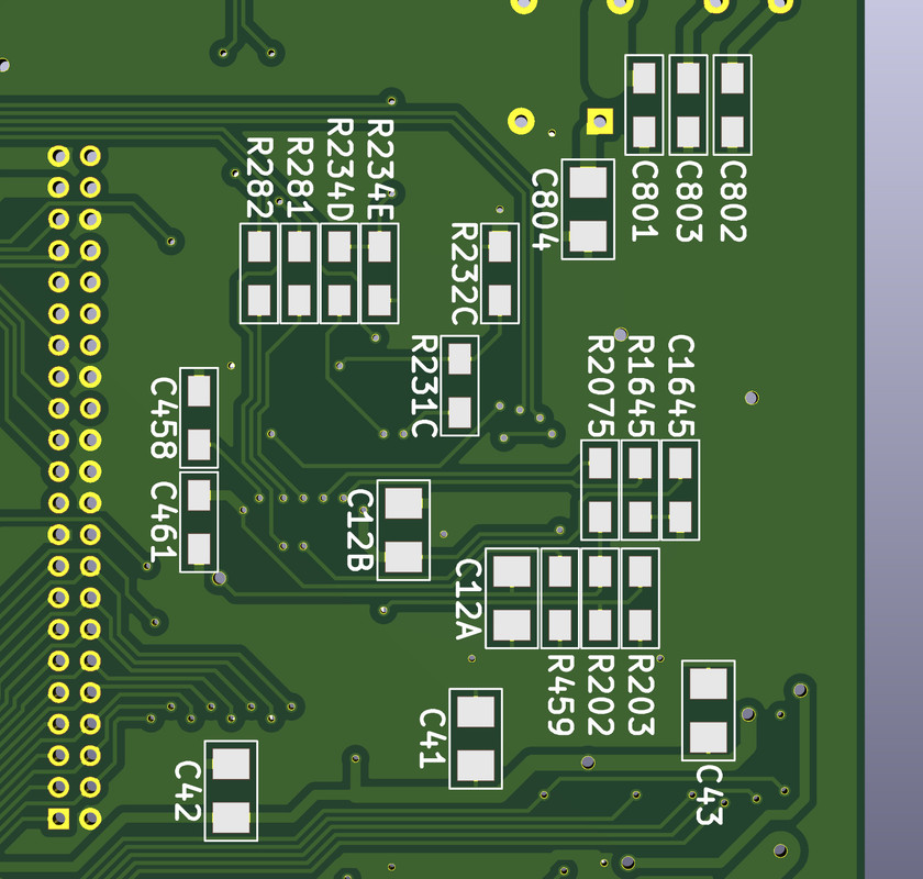
Last edited by Mick; 10 October 2020 at 14:54. |
|
|
|
11 October 2020, 17:58
|
#388 | |
|
Tinkerer
Join Date: Jan 2020
Location: NZ
Posts: 104
|
Quote:
|
|
|
|
|
13 October 2020, 17:21
|
#389 |
|
Registered User
Join Date: Aug 2019
Location: The Netherlands
Posts: 115
|
Hi Mick. Could you share your KiCad files on GitHub/GitLab? I can't find the files at The Zone, I know there is something wrong with my eyes, but not that bad
") Thanks in advance Thanks in advance 
|
|
|
|
13 October 2020, 22:40
|
#390 | |
|
Registered User
Join Date: Jan 2008
Location: United Kingdom
Age: 46
Posts: 733
|
Quote:
https://github.com/istedman/A600Reborn The board needs testing still, it's on my todo list. |
|
|
|
|
14 October 2020, 09:21
|
#391 |
|
Registered User
Join Date: Aug 2019
Location: The Netherlands
Posts: 115
|
Thanks Stedy!
|
|
|
|
15 October 2020, 10:49
|
#392 |
|
Registered User
Join Date: Jan 2004
Location: Yorkshire
Posts: 710
|
I will upload everything to the zone again and send stedy a new copy but preferably would like to get it working myself first given the time and effort I've put into it.
stedy, do you see any reason why this wouldn't work or might have problems? and if I get new boards would you test? I've separated the ram as much as possible, included a dual CXA1645/2075 footprint and added the modulator mounting holes for any mods that might use them. I've looked at rev2 boards as a guide to the video ground keep-out, rev1 have a bit more copper on top below the DAC...    
Last edited by Mick; 15 October 2020 at 11:02. |
|
|
|
19 October 2020, 20:44
|
#393 |
|
Registered User
Join Date: Jul 2017
Location: Germany
Posts: 205
|
"included a dual CXA1645/2075" ....excellent Mick, i hope your board will someday work. Its amazing how much time you have invested so far.
|
|
|
|
19 October 2020, 23:45
|
#394 |
|
Registered User
Join Date: Jan 2004
Location: Yorkshire
Posts: 710
|
I'm just compensating for those with the ability but who lack the will.
|
|
|
|
09 November 2020, 03:23
|
#395 |
|
Registered User
Join Date: Jul 2009
Location: UK
Posts: 112
|
@thread
Has anyone done a report on All Amiga motherboard parts/BOM Consolidation? So we can get faster and lower cost production ? [ Show youtube player ] |
|
|
|
09 November 2020, 08:22
|
#396 |
|
Registered User
Join Date: Oct 2017
Location: Germany
Posts: 193
|
I'm really impressed with how the design has come along ... well done ... Just a couple of points I noticed and wanted to ask if they have been considered;
1. Thermal reliefs around TH pads - soldering will be very difficult on multi layer PCBs without them. Have you considered adding this as an option in your ground plane? 2. Via hole size on power traces - i.e., between C41 and C43. Current will be mostly flowing through the hole plating - unless you are using a power plane. To be on the safe side, have you considered increasing the trace size around the via to ensure there is more trace copper? 3. Moving R102 so accelerators / FastRAM adapters can be added easier? |
|
|
|
10 November 2020, 22:22
|
#397 |
|
Registered User
Join Date: Jan 2004
Location: Yorkshire
Posts: 710
|
Hi PR77,
1> I had thermal reliefs on TH originally because it's Kicad default but if you look at some photos (I have extensively) Commodore didn't have them on the outer layers either and I'm trying to keep things as close as possible. Solid fills looks better on the outer layers but I understand it will make soldering more difficult. 2> I've followed original boards really closely and they are still alive after 25 years so I didn't think it would be necessary. Now you mention it though I did wonder if filling the via's with solder was for a reason? would it be necessary? 3> Yeah this was suggested before but accelerators are going to be sold with the socket cut out for original boards anyway and I'm kind of in the mindset of changing as little as possible now. I only did the CXA2075 because the Z221/Z222 and modulator are defunct. |
|
|
|
30 December 2020, 22:53
|
#398 |
|
Registered User
Join Date: Jan 2008
Location: United Kingdom
Age: 46
Posts: 733
|
Nearly end of the year, time for an update.
I've spent a fair few hours the last three days working on the first prototype. It doesn't work yet but I've learnt a few things on the way. My first mistake was aligning the 40 pin ROM socket with the pin 1 ident on the board, not on pin 2. I powered up the board (after checking for shorts) and the CPU and ROM got warm to the touch quickly. It took some time to notice the ROM socket was wrong. Unfortunately I've killed the DiagROM device I had. Just ordering another one from Ebay. The PCB drew 3.16A against an expected 1.6A, all the extra power went through the ROM! The numerous clocks appear to be Ok, got a bit confused when I could not see a 14MHz clock coming from Agnus, checked my working A600, that had no 14 MHz clock and the 14M input on Gayle actually has 7.09MHz! The problem I have now is that the _RST line is stuck @ 1.6V. The _kbreset works fine and it goes to GAYLE correctly. I'm wondering if something else, possibly the CPU is trying to drive the _RST signal as 1.6V is around mid-point if one device drives low and another tries to drive it high. Not sure if I damaged the CPU with an incorrectly inserted ROM, has anyone else damaged a CPU by incorrectly installing a ROM? Will test some more over the next few days as I'm not going out anywhere. Last edited by Stedy; 30 December 2020 at 22:54. Reason: Typo |
|
|
|
31 December 2020, 19:13
|
#399 |
|
Registered User
Join Date: Jan 2004
Location: Yorkshire
Posts: 710
|
Cheers for the work Stedy, any information is welcome so I can hopefully learn more. Maybe it's a manufacturing issue or just signal loss over distance? I dunno but _RST looks to be a really long trace that goes all over the place. I was pushing the limits of manufacturing for trace and via widths so that the autorouter wouldn't just get stuck in an infinite loop.

Last edited by Mick; 31 December 2020 at 19:25. |
|
|
|
01 January 2021, 13:32
|
#400 |
|
Mighty Pirate
Join Date: Dec 2017
Location: On the borderline
Age: 44
Posts: 177
|
The /RST signal is most likely driven in open-collector style. Did you install the corresponding pull-up resistor?
|
|
|
| Currently Active Users Viewing This Thread: 1 (0 members and 1 guests) | |
| Thread Tools | |
 Similar Threads
|
||||
| Thread | Thread Starter | Forum | Replies | Last Post |
| Legal: Amiga schematics | michaelz | support.Other | 25 | 15 March 2017 13:13 |
| First Amiga 600 FPGA Accelerator - Vampire 600 | majsta | Hardware mods | 736 | 18 July 2016 18:31 |
| aminet Clean schematics Amiga Classics | cosmicfrog | support.Hardware | 14 | 12 March 2016 20:03 |
| Amiga 2000 keyboard schematics | Brannigan | support.Hardware | 11 | 10 February 2014 08:24 |
| What if DCE donated Amiga Hardware Schematics? | Yoto | Retrogaming General Discussion | 47 | 15 May 2012 15:04 |
|
|


