
|
 13 January 2018, 17:42
|
#321 |
|
Registered User
Join Date: Aug 2017
Location: Poznan/Poland
Posts: 73
|
Kato, I'm from Poland too, so we can speak in Polish, I suppose:-) hahaha:-)
That problems in Settlers may be caused by wrong Gary adapter. I use Gary adapter from my design, which was adapted to the next PCB revisions of this extension (eg in Your rev4 PCB). My Gary adapter has small mistake in turn off circuit (512/more doesn't work), but works perfectly. I can give You PCB for my Gary adapter if You want, because I have few more. Send me PM here or on ppa.pl (You can in Polish:-)). |

|
|
14 January 2018, 09:50
|
#322 |
|
-
Join Date: Jul 2003
Location: Helsinki / Finland
Age: 43
Posts: 9,900
|
.. but please speak Polish in PM, the board is in English. :-)
|

|
|
14 January 2018, 11:03
|
#323 |
|
Registered User
Join Date: Jan 2018
Location: Poland
Posts: 3
|
A500 trapdoor memory: free design
Mq - thanks, I will be able to talk to you soon
 . For now, I am still waiting for other integrated circuits that are to come to me on the days, so I will try again on my pcb B.4. . For now, I am still waiting for other integrated circuits that are to come to me on the days, so I will try again on my pcb B.4.Jope - surely Mq meant PM, we respect the forum very much I am sorry if I write something wrong in English, but I'm not a language specialist That's why I am asking you for your understanding
|
|
|
|
14 January 2018, 12:25
|
#324 |
|
-
Join Date: Jul 2003
Location: Helsinki / Finland
Age: 43
Posts: 9,900
|
There is no need to apologise, most of us (me included) are not native English speakers here.
|
|
|
|
24 January 2018, 10:28
|
#325 |
|
Mighty Pirate
Join Date: Dec 2017
Location: On the borderline
Age: 44
Posts: 177
|
Still waiting for some components to arrive to finalize my build. Anyway I was wondering what happens if I plug a board with the RTC circuit in a 500+: will it override the internal RTC straight away or do I have to change anything on the mainboard? I'm asking since my battery leaked, so I have removed it and have had to repair like 20 traces, so I'd rather not keep a battery in it anymore.
|
|
|
|
24 January 2018, 18:14
|
#326 |
|
Posts: n/a
|
---Expansion Board B6
RTC: RTC72421 B EPSON Chip Memory 4x KM416C1204AJ-6 SEC 1x 74HC139D NXP (yes 74HC139D Working) C11 = 10µF ±10% 16V Tantalum (I did not have 4.7uf) D1 = BAT54C or KL3 0.2A/30V SOT23 Schottky Various Resistor And Capacitor ---GARY 3x 74HC00D NXP 1x 74HC74D NXP ------Config A500 4chip Memory (1MB chip : 1.5MB Slow)---------- Amiga Rev 6A with AGNUS 8372A KICK 1.3 Cut JP2 : see pictures 1 and 2 (Amiga board) there is a connection (middle pin and pin down) CUT 4 Wires CAS1L, CAS1U, CAS2L, CAS2U --> XCAS (Expansion Board) All Jump RAS1 EXRAM Enable CLOCK Enable (if have RTC) ----Gary Adaptor--- View Picture 3 for position JUMPER Picture 4 for wire Gary to Expansion Board ********************************** Thanks to PeteAU, Mathesar, Mq  ********************************** Next step ... TerribleFire,  I expect components...        
Last edited by kamikaze38; 24 January 2018 at 18:17. Reason: add link |
|
25 January 2018, 09:57
|
#327 | ||
|
Registered User
Join Date: Dec 2016
Location: Australia
Posts: 113
|
Quote:
Quote:
Last edited by PeteAU; 25 January 2018 at 10:33. |
||
|
|
|
25 January 2018, 10:31
|
#328 |
|
Registered User
Join Date: Nov 2016
Location: Norway
Posts: 7
|
I bought some 72-pin RAM off ebay, was sure it was the correct kind, but turned out to be soj40 instead of soj42. Am I screwed? (I googled the soj40, and it seems they use them for the A600 piggyback mod. 2 chips for 1MB extra Chip RAM)
|
|
|
|
25 January 2018, 13:00
|
#329 | |
|
Posts: n/a
|
Quote:
Hi PeteAU Yes all chips is CMOS HC not HCT Working
|
|
|
27 January 2018, 00:30
|
#330 |
|
A-Collector, repairments
Join Date: Jul 2001
Location: Czech Rep.
Age: 50
Posts: 1,536
 |
Ordered 5 pcs, got 8pcs
looks like some chinese operator wants to make ten of them, but stopped it at last  way to go elecrow 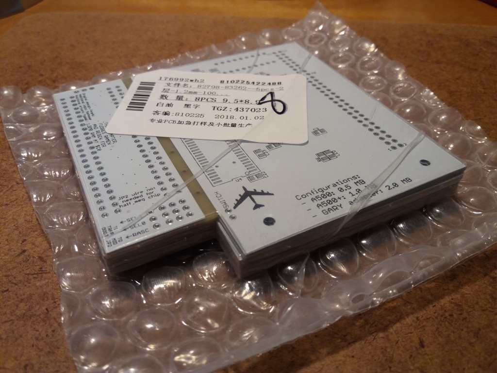   |
|
|
|
27 January 2018, 02:36
|
#331 |
|
Registered User
Join Date: Jan 2018
Location: Gloucester
Posts: 83
|
Like the B52! - a nice touch

|
|
|
|
29 January 2018, 09:20
|
#332 | ||
|
Registered User
Join Date: Dec 2016
Location: Australia
Posts: 113
|
Quote:
Quote:
|
||
|
|
|
01 February 2018, 20:55
|
#333 |
|
Registered User
Join Date: Dec 2015
Location: Nottingham
Posts: 19
|
I have an expansion slot in mine but from what I can tell about the official ones is that they are in a metal box, this one isn't, its an obvious 3rd party after market what-cha-ma-call-it and it has a switch on it that lord knows what it does. Dispenses fun size crunchy bars from the vending machine on the IIS or something...
So any ideas on what the switch does? |
|
|
|
01 February 2018, 21:49
|
#334 |
|
Registered User
Join Date: Aug 2017
Location: Poznan/Poland
Posts: 73
|
@kamikaze38: congratulations, good work!
About HC cmos IC's: I saw in many projects people use them and they works with TTL signals usually. I was testing HC series in the RAM extension for Atari 65XE, and they works for me too. HC cmos has different levels of high and low, but I noticed if we give them signals which fits in the high and low levels, then they works the same as HCT. If we give supply voltage 5V, then they give us proper levels accepted by TTL's too. HCT are actually near same as HC, but with signal levels matched to TTL. |
|
|
|
01 February 2018, 22:44
|
#335 | |
|
Unregistered User
Join Date: Sep 2012
Location: Copenhagen / DK
Age: 44
Posts: 4,190
|
Quote:
|
|
|
|
|
08 February 2018, 04:57
|
#336 | |
|
Registered User
Join Date: Nov 2016
Location: Norway
Posts: 7
|
Quote:
|
|
|
|
|
08 February 2018, 05:11
|
#337 | |
|
Registered User
Join Date: Dec 2016
Location: Australia
Posts: 113
|
Quote:
|
|
|
|
|
09 February 2018, 03:16
|
#338 |
|
Registered User
Join Date: Nov 2016
Location: Norway
Posts: 7
|
Wow! Thats awesome! Thanks! Due to chinese new years, it might take a while untill I get my PCBs, but Ill let you know how it goes! Can I just use this the same way as the soj42 pcb?
|
|
|
|
25 March 2018, 11:25
|
#339 |
|
Mighty Pirate
Join Date: Dec 2017
Location: On the borderline
Age: 44
Posts: 177
|
I have finally tested the boards I received from Mathesar in the following configurations:
- 1 MB chip on A500+ - 512 KB slow on A500 Rev.6A Both are working great, both for the extra memory and for the RTC. Now I've built a Gary adapter and added 3 more RAM chips on the 512 KB expansion to get 1 MB chip + 1.5 MB slow on the 500, but then I realized I'm still missing the '139, so I will have to wait even more, grrr! Anyway, could anyone recommend how to set the various RAS jumpers to achieve this? Oh and what's the 512K/More jumper exactly for? I think it would be a good idea to add a table of the most commonly used jumper settings in the first post. Another thing: I have imported the design in Kicad and made some changes: I have removed all the hardwired jumper connections since I prefer to solder real jumpers and set them as needed (@katarakt will like this!). I have also improved the ground plane a bit, mainly on the Gary adapter. Kicad did a good a job (for the PCB at least, not as much for the schematics...), but it messed up the whole silkscreen (had to manually fix almost every label!) and it failed to import the disk and B52 images. Could anyone provide those as plain images so that I can reimport them manually? Thanks. PS: Of course I plan to contribute my modified PCB once it's tested. Last edited by SukkoPera; 25 March 2018 at 12:49. |
|
|
|
25 March 2018, 17:13
|
#340 | |
|
Registered User
Join Date: Jul 2017
Location: Germany
Posts: 205
|
Quote:
And yes, i like this with removed hardwired jumpers! I've also removed them in my pcbs . Don't know if they're working because still waiting for one part (i've ordered 3 components wrong). I don't know why these are all hardwired in original layout  The 512/More jumper i think is if you want to turn the ramexpension off completely. If you turn of only the ram expansion, gary is still active with more memory as i know (also an information somewhere in this thread if i remember correctly). Still some optimization needed to the board for future revision: - C20 change lead space straight from 2.5mm to 2mm because every better capacitor has 2mm with fits there in diameter! - Remove these hardwired jumper traces - add a wire from the LED resistor to 3 pin so we can use a 3-pin connector and a switch with integrated LED or put a seperated LED somewhere anywhere we want with connectors (see picture below) ...or mybe is a 4-pin better if i want to sperate LED and switch....hmmm....what do you think ? edit: i think 4-pin is better, because in that way for example you can put led on the top and switch on the back on amiga, so everyone can put switch and LED wherever he wants
Last edited by katarakt; 25 March 2018 at 21:17. Reason: see edit |
|
|
|
| Currently Active Users Viewing This Thread: 1 (0 members and 1 guests) | |
| Thread Tools | |
 Similar Threads
|
||||
| Thread | Thread Starter | Forum | Replies | Last Post |
| Modern Trapdoor RAM killed my A500 | Silwuff | New to Emulation or Amiga scene | 20 | 10 January 2021 15:36 |
| Homemade A500 trapdoor expansion? | cabal | Hardware mods | 5 | 01 December 2014 21:44 |
| WTB: two(2) A500 trapdoor slot covers | papa_november | MarketPlace | 0 | 25 December 2008 09:17 |
| Trapdoor expansion options for A500 | Impakt | support.Hardware | 7 | 20 March 2008 06:05 |
| A500 Plus Trapdoor Expansion | TheCorfiot | support.Hardware | 10 | 14 March 2008 16:42 |
|
|


