
|
 06 January 2020, 14:45
|
#241 | |
|
Tech Guru
Join Date: Dec 2015
Location: Oxnard, CA
Posts: 189
|
Quote:
This was given to me, so no charge to who it goes to next. Maybe just shipping if overseas. |
|

|
|
06 January 2020, 14:49
|
#242 | |
|
Tech Guru
Join Date: Dec 2015
Location: Oxnard, CA
Posts: 189
|
Quote:
|
|
|
|
|
06 January 2020, 15:01
|
#243 |
|
Registered User
Join Date: Jan 2004
Location: Yorkshire
Posts: 734
|
Ok thanks Steve, do you mean yours should be correct or do you think I need to change the way Commodore did it for the 2075?
I have just realised something else that might be causing a problem with video output, the 2.61K resistor for the YTRAP needs to be a 1% resistor so it needs to be accurate, but if you look at the schematics I don't have it connected directly to VCC but VID which goes through the 4.7Ohm 5% resistor (R406) first. Does this mean the internal circuity isn't being enabled or will it be okay because it's still within 1% of 2.62K? Last edited by Mick; 06 January 2020 at 15:07. |
|
|
|
06 January 2020, 15:04
|
#244 | |
|
Registered User
Join Date: Jan 2004
Location: Yorkshire
Posts: 734
|
Quote:
Last edited by Mick; 06 January 2020 at 15:17. |
|
|
|
|
07 January 2020, 01:25
|
#245 | |
|
Registered User
Join Date: Jan 2008
Location: United Kingdom
Age: 46
Posts: 733
|
Quote:
I'm still working through schematics and layout, no issues yet though I will double check how the vagarious parts get fitted to route clock signals. Will collate the post-it notes and get back to you. A review like this takes 6-8 hours so I'm doing it over a few evenings. @Acill What would it cost to ship the prototype PCB to the UK? I could take a look, would be toward the end of the month as I have two smaller projects to clear first. I have Diagrom for A500/A600 for when I get around to fixing my dead A500 that might prove useful. Also have oscilloscope and logic analyser 
|
|
|
|
|
07 January 2020, 06:41
|
#246 |
|
Registered User
Join Date: Dec 2018
Location: Sydney / Australia
Posts: 96
|
Video output (or lack thereof) is not really important in preliminary board bring-up. A DiagROM and serial output would probably be a good starting point to know if the board is "alive".
One would not even load the video output parts at this point. |
|
|
|
07 January 2020, 13:33
|
#247 |
|
Registered User
Join Date: Jan 2004
Location: Yorkshire
Posts: 734
|
I'll pay the postage to Stedy if Acill tells me how much and PM me his PayPal address.
Stedy, if you want I can send you latest files, I've added extra memory and clockport which was easy enough. The only thing that confused me was the _PWR_BAD signal where do I get it from? I've removed the PAL for now to try to keep things simple. 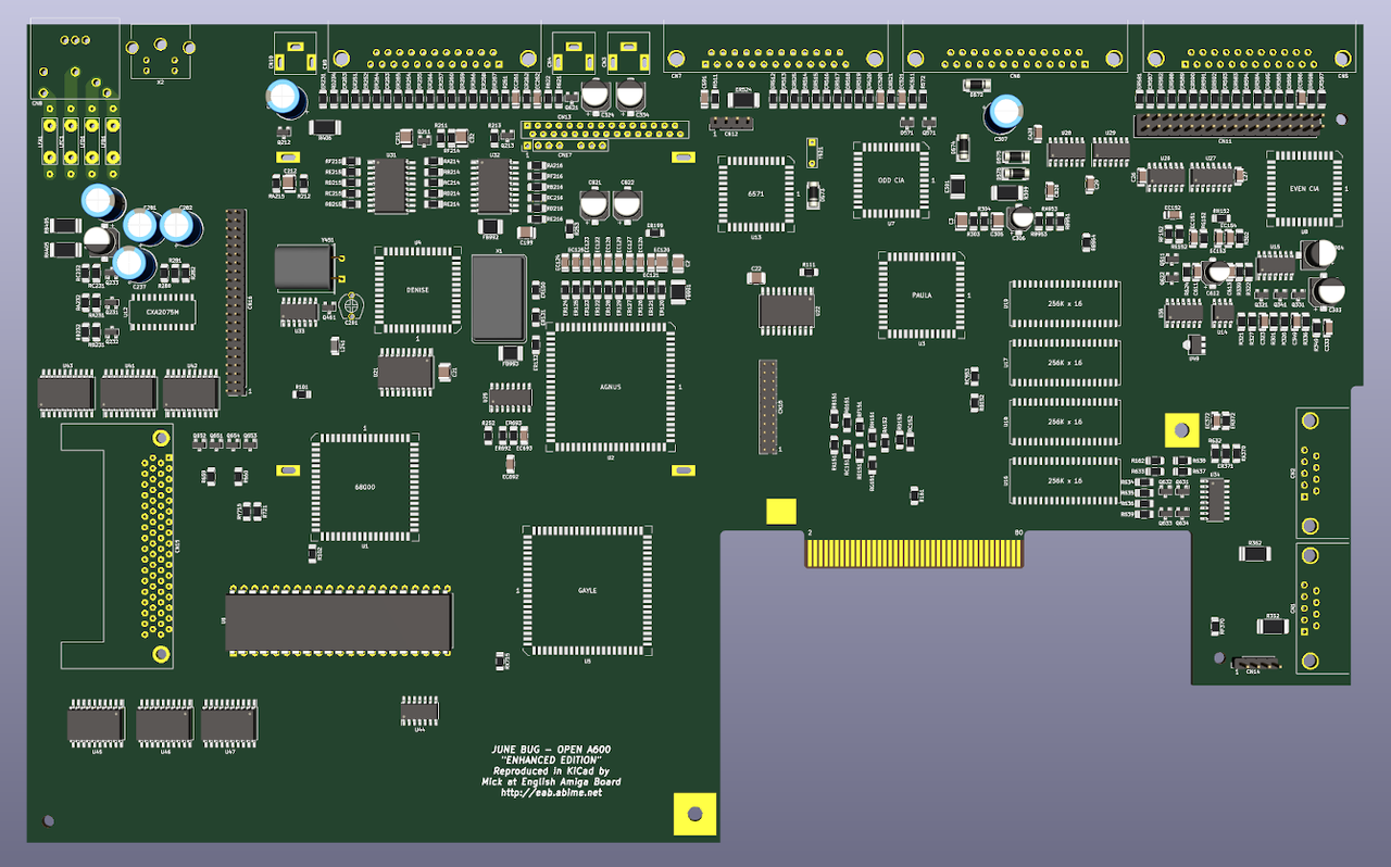 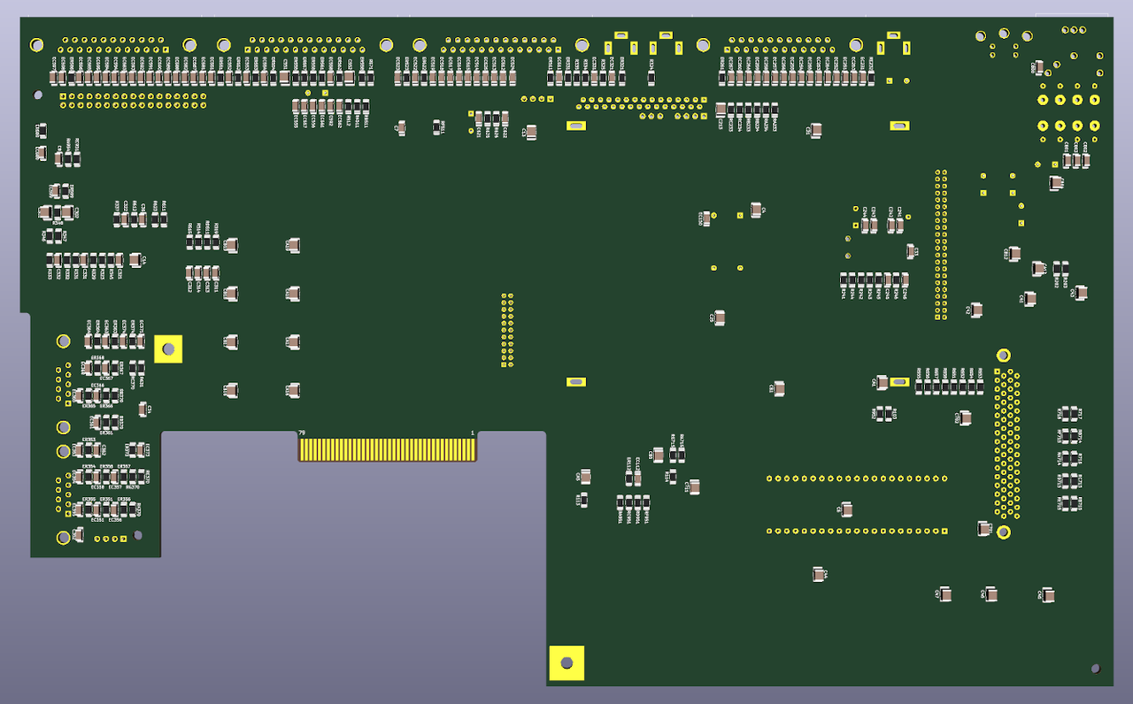 I am not even that bothered about an A600 motherboard unless new cases are made but it feels like some kind of crusade at this point, I've put so much into it I want to see it complete.  
|
|
|
|
08 January 2020, 13:20
|
#248 |
|
Registered User
Join Date: Jan 2004
Location: Yorkshire
Posts: 734
|
Ok so a theoretical situation, if you have 2MB onboard with the last 1MB using the same signals as the expansion connector what would happen if you also plugged in a 1MB expansion? would there be some sort of conflict?
|
|
|
|
08 January 2020, 14:46
|
#249 |
|
-
Join Date: Jul 2003
Location: Helsinki / Finland
Age: 43
Posts: 9,910
|
Yep, it wouldn't be a stable configuration with two chips being selected for the same memory area.
|
|
|
|
08 January 2020, 15:50
|
#250 |
|
Registered User
Join Date: Jan 2004
Location: Yorkshire
Posts: 734
|
I was just thinking because of things like the A314 project it probably would not be compatible in that case.
Do you think a CPU/fast ram accelerator could be made small enough to fit in the A600 expansion area if I turned the edge connector into a a500 style zorro? I'm kind of just messing around with ideas at this point until I can find out what is wrong with Acill's board. Otherwise, what would be the best way to disable the second megabyte? jumper? Last edited by Mick; 08 January 2020 at 17:42. |
|
|
|
08 January 2020, 18:19
|
#251 |
|
-
Join Date: Jul 2003
Location: Helsinki / Finland
Age: 43
Posts: 9,910
|
A RAS jumper similar to JP3 on the Rev6-8 A500 board perhaps?
|
|
|
|
08 January 2020, 20:09
|
#252 |
|
Registered User
Join Date: Jan 2004
Location: Yorkshire
Posts: 734
|
I'll do that then.
 Do you have any idea what R162 does? it connects to the expansion connector and is labelled _X1M. |
|
|
|
08 January 2020, 23:37
|
#253 |
|
Registered User
Join Date: Jan 2004
Location: Yorkshire
Posts: 734
|
There's a bit of a problem with that way I think, the A600 has its two memory chips split between RAS 0 and 1 instead of on the same row and so do the expansions so if I disable one row on the board I think when you plug in an expansion it'll have 3 chips active on one row and only 1 on the other. I'll need to disable one chip on each row. I guess I'll need two jumpers before the second chips on each row?
Last edited by Mick; 08 January 2020 at 23:45. |
|
|
|
09 January 2020, 00:58
|
#254 |
|
Registered User
Join Date: Jan 2008
Location: United Kingdom
Age: 46
Posts: 733
|
Hi,
Still checking through the schematics, might have found something. Does the prototype A600 board have a working 6570 Keyboard microprocessor? If that chip is missing or the 3MHz crystal does not start, the A600 will not generate the 500ms power on reset signal, via kb_reset. The MC68000 must be held in reset for 100ms to operate correctly. Will draw out a few critical circuit to check them. Looking for the custom chip documents on my hard drive. Last edited by Stedy; 09 January 2020 at 00:59. Reason: Hit enter too soon. |
|
|
|
09 January 2020, 11:36
|
#255 |
|
Registered User
Join Date: Jan 2004
Location: Yorkshire
Posts: 734
|
I've got no idea Stedy all I've really been told is it doesn't work.
If that's the case the keyboard controller is absolutely necessary then? there's not really much point in having the A500 keyboard connector in that case. Is the A1200 the same? Once again thanks for the help. Last edited by Mick; 09 January 2020 at 13:16. |
|
|
|
09 January 2020, 13:42
|
#256 | |
|
Registered User
Join Date: Dec 2018
Location: Sydney / Australia
Posts: 96
|
Quote:
I'm not sure if that is correct. From my reading of the schematic, _RST is generated by GAYLE, and this depends on the signal _KB_RESET which is an input to GAYLE. The _RST signal is the system-wide reset and also keeps the 6570 in reset. The machine begins in a reset state (Q511 is ON) and _KB_RESET is de-asserted by the 555 (U14) output when it reaches its timeout (0.1uF capacitor charging via a 47K resistor to reach the threshold voltage). GAYLE de-asserts its output _RST once its input _KB_RESET (driven by the 555 and output BJT Q511) is de-asserted. This then brings the 6570, CPU and the rest of the machine out of reset. The 6570 can generate a new reset at any time by re-triggering the 555. However the 6570 is not required to bring the machine out of reset and the machine should function correctly without it. Of course if the 6570 is not loaded, then Q622 should not be loaded either, otherwise it will hold the machine in reset. R624 is also not meant to be loaded. |
|
|
|
|
09 January 2020, 19:52
|
#257 |
|
Registered User
Join Date: Jan 2004
Location: Yorkshire
Posts: 734
|
I spent a while comparing the schematics on Amigawiki to an original Commodore document and found quite a few discrepancies. Will any of these cause major problems?
E353R 47 not 68 E354R 47 not 68 E363R 47 not 68 E364R 47 not 68 C321 100nF not 3900pF R321 360 not 1.5K C331 100nF not 3900pF R331 360 not 1.5K R325 390 not 2K R335 390 not 2K C26 0.01uF not 0.047uF C27 0.01uF not 0.047uF C33 0.01uF not 0.047uF C34 0.01uF not 0.047uF C7 0.01uF not 0.047uF C8 0.01uF not 0.047uF C29 0.01uF not 0.047uF C28A 0.01uF not 0.047uF C28B 0.01uF not 0.047uF C36 0.01uF not 0.047uF These were mistakes by me I think: E513R 68pF not 47pF E514R 68pF not 47pF E515R 68pF not 47pF E516R 68pF not 47pF I'm not sure about these: On the internal floppy connector all 27 ohm resistors should be 68? Are there any original Commodore schematics for rev. 2 so I can check the floppy section? or can anyone with an actual board handy check them please? the ones in question are E586R, E596R, E580R, E595R, E599R, E593R, E592R, E591R, E590R, E589R, E588R, E582R, E587R, E581R, E594R, E583R, E584R, E585R. I want to know if they're 27 or 68. I've looked at a photo of a 2B board and they don't have any markings. Actually they look a lot more like ferrite beads used elsewhere. Last edited by Mick; 09 January 2020 at 20:13. |
|
|
|
09 January 2020, 23:18
|
#258 |
|
Registered User
Join Date: Oct 2019
Location: Melbourne/Australia
Posts: 39
|
Hi Mick,
I have a rev 2B (or is it 2D A600 board?, i'll have to check). I remember going through a few resistors on my board, and found that the resistors on my board were different to the values on PCB explorer. I know that on my board, there are more 27 ohm resistors on the floppy than there are 68 ohm. Just looking now, I notice that the R2 schematics from amigawiki look to be a better fit to my board, but I will double check when I get home. But I wont be home until Saturday afternoon (Australia time). Hope you can hang out that long  If you want some close up photos of the board, let me know. Cheers |
|
|
|
10 January 2020, 00:36
|
#259 |
|
Registered User
Join Date: Jan 2004
Location: Yorkshire
Posts: 734
|
I think 2B and 2D are a bit different but any info you can give will help me get a better understanding.
The Commodore schematics I looked at appeared to be for rev. 1 but those parts above differed to both Amigawiki rev. 1 and rev. 2 documents (the wiki documents matched one another but were different to Commodore). The floppy section for rev. 1 seems to be a lot different to rev. 2, the signals are all connected to the internal floppy connector directly on rev. 1? it'd be nice to see original rev. 2 schematics but doesn't look like they're anywhere. The 2B board I was looking at was this: https://www.bigbookofamigahardware.c...0mbrev2b_1.jpg There's no markings at all on those. Last edited by Mick; 10 January 2020 at 00:46. |
|
|
|
10 January 2020, 00:53
|
#260 |
|
Registered User
Join Date: Oct 2019
Location: Melbourne/Australia
Posts: 39
|
Yep, see what you mean, I only have the rev 1 schematics too. Rev 2 seems elusive, apart form the amigawiki one.
When I get home this weekend, I'll take some close up pics of the rev 2 board I have, but mine definitely has resistors on the floppy section, not ferrite beads like the BBOAH pic. Once I get the pics, i'll try and post here. If you need pics of the bottom, let me know. |
|
|
| Currently Active Users Viewing This Thread: 1 (0 members and 1 guests) | |
| Thread Tools | |
 Similar Threads
|
||||
| Thread | Thread Starter | Forum | Replies | Last Post |
| Legal: Amiga schematics | michaelz | support.Other | 25 | 15 March 2017 13:13 |
| First Amiga 600 FPGA Accelerator - Vampire 600 | majsta | Hardware mods | 736 | 18 July 2016 18:31 |
| aminet Clean schematics Amiga Classics | cosmicfrog | support.Hardware | 14 | 12 March 2016 20:03 |
| Amiga 2000 keyboard schematics | Brannigan | support.Hardware | 11 | 10 February 2014 08:24 |
| What if DCE donated Amiga Hardware Schematics? | Yoto | Retrogaming General Discussion | 47 | 15 May 2012 15:04 |
|
|


