|
 16 June 2024, 12:41
|
#41 | |
|
Registered User
Join Date: Jun 2010
Location: PL?
Posts: 2,879
|
Quote:
They are part of Current to Voltage converter (4 DAC's in Paula produce current not voltage and current must be converted in I/V converter - this is emphasized on schematics by using iRight/iLeft description). Many resistive DAC's are current output type and in many CD's/DAC's this conversion is performed by fancy solutions (like OPA861 fast OTA even if in theory they are simpler than Paula - no PWM level regulation). |
|

|
|
16 June 2024, 15:17
|
#42 |
|
Registered User
Join Date: Jan 2004
Location: Yorkshire
Posts: 741
|
but those resistors to ground aren't present on the A600 and A1200? I was just wondering if Commodore were taking sound quality a bit more seriously when designing the CD32.
Last edited by Mick; 16 June 2024 at 15:35. |
|
|
|
16 June 2024, 19:08
|
#43 | |
|
Registered User
Join Date: Jun 2010
Location: PL?
Posts: 2,879
|
Quote:
|
|
|
|
|
16 June 2024, 19:57
|
#44 |
|
Registered User
Join Date: Jan 2004
Location: Yorkshire
Posts: 741
|
I was thinking of just bodging in a couple of resistors at some point to see if there's any improvement but from what I gather it will create a voltage divider with the "NOISE" and "AUDIN" inputs so I guess it's not going to be as simple as that.
Do you think OPA657 in the first stage would make any improvement? |
|
|
|
16 June 2024, 23:30
|
#45 |
|
Registered User
Join Date: Jun 2010
Location: PL?
Posts: 2,879
|
It may improve linearity but such high speed OPMP are tricky - you need very good PCB layout and proper decoupling (check datasheet for recommended layout), also it is not able to operate at +-5V power supply. This is my impression that without significant PCB layout changes you can't squeeze max from Paula. Simple OPAMP swap may not work even if OPAMP in theory should deliver way better results.
|
|
|
|
17 June 2024, 22:53
|
#46 |
|
Air supremacy
Join Date: Aug 2008
Location: Rijeka Croatia
Posts: 125
|
Great thread.
@Pandy71 I guess placing AD713 instead of LF347/TL084 would not provide any benefits ? Thnx. |

|
|
18 June 2024, 22:55
|
#47 | |
|
Registered User
Join Date: Jun 2010
Location: PL?
Posts: 2,879
|
Quote:
It could be interesting to try passive lowpass (25..35kHz) Bessel LC filter before I/V conversion - it may significantly improve conditions and OPAMP's like AD713 can be sufficient. |
|
|
|
|
18 June 2024, 23:19
|
#48 |
|
Air supremacy
Join Date: Aug 2008
Location: Rijeka Croatia
Posts: 125
|
Thnx.
|
|
|
|
19 June 2024, 10:42
|
#49 | ||
|
Registered User
Join Date: Jan 2004
Location: Yorkshire
Posts: 741
|
Quote:
I am now wondering if something like the Linear LT1359 as a drop in replacement is worth a punt? I know you've said the OP AMP probably won't make a difference without a new layout but I'm just interested to try something better. As I understand it op amps tend to have different sound signatures anyway. My current plan is: Bodge in board with 5V regulator for Paula and LM4040 VREF. Replace all resistors in audio path with thin film. Replace R301/R302 with ferrite beads. Replace E321R/E331R with ferrite beads (same as CD32). Try a better OP AMP. If that doesn't show any improvement then it's been a rather expensive experiment. Quote:
Last edited by Mick; 19 June 2024 at 10:51. |
||
|
|
|
19 June 2024, 20:29
|
#50 | ||||
|
Registered User
Join Date: Jun 2010
Location: PL?
Posts: 2,879
|
Quote:
Quote:
Lot of people claim to heard audible difference when they replacing power socket in their wall for gold plated or using special interconnects made from ruthenium. I'm not so golden ear so from my perspective if cost is not too high then it is fine - almost sure that better OPAMP will not destroy anything or make it worse. Quote:
Additionally i would add some linear voltage regulators (LDO's?) on audio power lines so introduce additional separation from noise and ripples present on power lines (R301/R302 seem to be good point to introduce such modification) - something like high PSRR, low noise (for example LT3093, LT3046). Quote:
Quickest way to improve audio quality is properly decouple power and reference - using ferrite beads instead resistors (E321R/E331R, R301/R302) for sure is a proper step. |
||||
|
|
|
19 June 2024, 20:29
|
#51 |
|
Registered User
Join Date: Jan 2004
Location: Yorkshire
Posts: 741
|
Is it known how much current Paula outputs for simulating? I'm guessing the feedback capacitor/resistor may be tailored specifically to the TL084?
|
|
|
|
20 June 2024, 13:35
|
#52 |
|
Registered User
Join Date: Jan 2004
Location: Yorkshire
Posts: 741
|
Half installed, I have to wait a few days for some parts to come in stock though.
I used Circuitlab and managed to get the first stage op amp output to align with the measurements in that Youtube video using around 3.15ma output but then when I added the later voltage divider and tried to match to his RCA readings it didn't align, so any help? I'm not very good with the electrical stuff. 
Last edited by Mick; 24 June 2024 at 19:05. |
|
|
|
21 June 2024, 10:09
|
#53 |
|
Registered User
Join Date: Jan 2004
Location: Yorkshire
Posts: 741
|
I'm just going to play it safe with TLE2074 for now, if all of the above doesn't make any audible improvement then it's fair to say Commodore did a really good job with the audio.
edit: so it turns out the TLE2074 is an extra wide package and probably won't fit. If only I'd realised before ordering.  2nd edit: I've ordered a LT1359, sold half of my Amiga collection in recent months to fund this. Oh well. 
Last edited by Mick; 21 June 2024 at 20:58. |
|
|
|
23 June 2024, 14:46
|
#54 |
|
Registered User
Join Date: Jun 2010
Location: PL?
Posts: 2,879
|
Perhaps too late but it would be nice to document all those modifications with measurements - simple capture from Amiga audio RCA output with help of PC audio card Line-in should be fine. This could provide some systematic approach to all modifications around Paula to improve audio quality.
How much is today LT1359? 10$ per piece? Or more? After Linear Technology was acquired by Analog Devices their parts prices raised significantly - same as Altera after acquisition by Intel... |
|
|
|
23 June 2024, 17:49
|
#55 |
|
Registered User
Join Date: Jan 2004
Location: Yorkshire
Posts: 741
|
Yeah I intended to take some screenshots with Audacity but then rather stupidly, when the bodge in board arrived I was eager to test if it fit. So all we have of stock system is the captures above where I clipped the silent parts. I would guess that if there's no distinct improvement then nobody will go through the trouble to mod their boards anyhow.
LT1359 was £15 but I figured if that isn't an improvement then nothing will be and plus it helped me to get free postage anyway so I saved £12, the other alternative was OPA4992 but the slew rate was lower than the TLE2074. I planned to sell my A600 anyway until this project popped up (it's a good way to learn more). Hopefully I'll get my money back in the end. Last edited by Mick; 23 June 2024 at 18:01. |
|
|
|
24 June 2024, 13:48
|
#56 |
|
Registered User
Join Date: Jan 2004
Location: Yorkshire
Posts: 741
|
I've got over 12V going into the regulator and 1.6V coming out, how much current does Paula draw?
edit: I've bodged in a 1.5A 7805 and it's now working. 
Last edited by Mick; 24 June 2024 at 14:11. |
|
|
|
24 June 2024, 17:08
|
#57 |
|
Registered User
Join Date: Jan 2004
Location: Yorkshire
Posts: 741
|
BEHOLD.
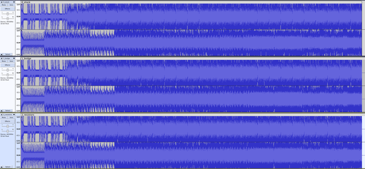
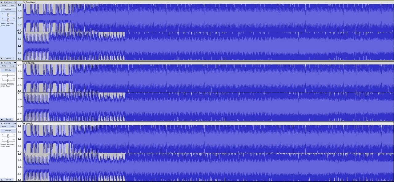
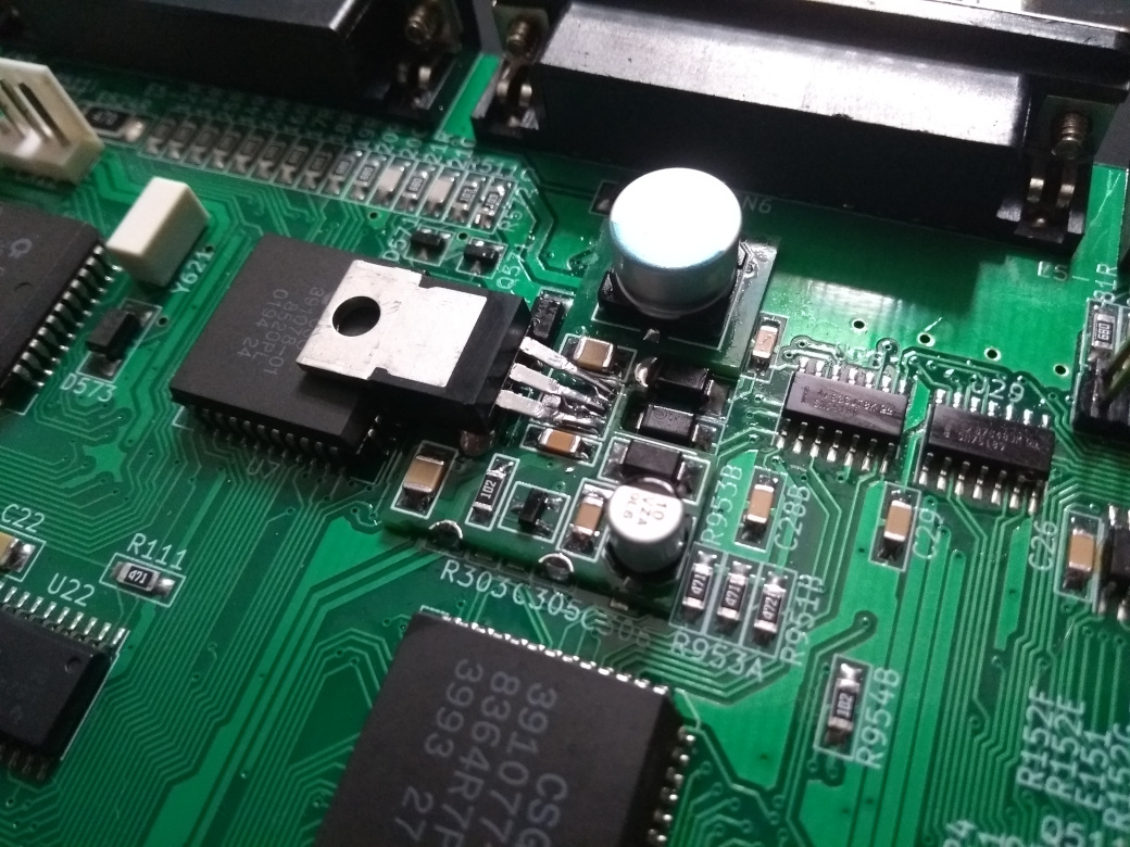 Alright, in the end all of the audacity captures looked more or less the same so I just made audio clips at different stages. IMO if anything the 0.1% small film resistors probably made the biggest difference but maybe there are some audiophiles with high end gear who can give the clips a good listen and provide some expert feedback. I think that Commodore did a really good job. VREF went from just under 2.4v to nearly 2.5V for what it's worth. Each stage also includes the parts from the previous stages. https://ufile.io/f/4gxj2 0_stock = stock a600 configuration. 1_bodge = 5V regulator to Paula and LM4040 for VREF. 2_resistors = 0.1% thin film resistors in audio path instead of stock 5% thick film. 3_ferrites = ferrite beads at R301, R302, E321R, E331R. 4_opamp = high end LT1359 op amp with a slew rate that's off the scale. Last edited by Mick; 24 June 2024 at 17:22. |
|
|
|
24 June 2024, 18:15
|
#58 |
|
Registered User
Join Date: Jan 2004
Location: Yorkshire
Posts: 741
|
|
|
|
|
24 June 2024, 21:15
|
#59 |
|
Registered User
Join Date: Jun 2010
Location: PL?
Posts: 2,879
|
They look clipped (but i didn't downloaded flac files - admit i was unable to deal with file service rules - use The Zone for temporary - 60 days uploads).
I would also record active silence - i.e. playing audio file with silence s noise floor will be visible and for example sinewave 1kHz with level like -3dBFS so you can easily set recording level (normalize) - i assume now it is too late for this. Fast OPAMP should help with 14 bit mode where two channels are combined to play higher bit depth sources - so it could be nice to record 14 bit mode before and after replacing OPAMP (calibration process recommended for both) |
|
|
|
24 June 2024, 23:11
|
#60 |
|
Registered User
Join Date: Jan 2008
Location: United Kingdom
Age: 46
Posts: 734
|
Hi,
You don't need a faster op-amp, quite the reverse. For an op amp maximum slew rate is 2*pi*V*fs, where V is the peak voltage (2.2V) and Fs is 20KHz (Audio range) . Multiply this together and you get 251327 volt/second. Divide by 1E6 to get V/us and you get 0.25v/us, the antique 741 Op Amp could handle Amiga audio (0.5v/us) and the TL084 has a slew rate of 20V/us. Paula has a current mode output, hence the I/V converter in the first amplifier circuit, I guess around 8mA into 360 ohms creates the output voltage. These are nice, linear D/A converters, they can work fast, not needed in this application. All this talk of PWM is nonsense, this is not a PCM output, as used on more modern sound cards, it's older technology. The audio circuit, in the Amiga, in simulations, shows the cut-off of the I/V converter around 27 KHz but the filter circuit, does add gain around 1MHz due to the 3900pF capacitors in the filter adding a zero in the feedback circuit, increasing the gain at 1Mhz then tailing of at 10MHz, the gain bandwidth of the TL084. So frequencies around 1Mhz will be amplified slightly to -6db instead of the -34dB they should have been rather than attenuated by. Never use a faster op-amp than you need as the higher frequencies can bite you in the bum. |
|
|
| Currently Active Users Viewing This Thread: 1 (0 members and 1 guests) | |
| Thread Tools | |
 Similar Threads
|
||||
| Thread | Thread Starter | Forum | Replies | Last Post |
| Modified Audio Filter | CHRIS-F | support.Hardware | 11 | 29 January 2017 23:42 |
| Tools for set FILTER OFF audio | jhonny82 | support.Games | 14 | 22 July 2015 16:06 |
| A600 Audio Filter Always On! | h0ffman | support.Hardware | 15 | 08 September 2013 22:29 |
| Feature request (Audio Filter) | DaveMB | support.FS-UAE | 16 | 20 August 2013 21:53 |
| Audio filter force on/off switch | TomCrazy | Hardware mods | 12 | 02 November 2012 14:18 |
|
|