
|
 04 May 2024, 00:38
|
#1 |
|
Registered User
Join Date: Oct 2007
Location: ManCave, Canada
Posts: 1,615
|
for GND do I connect it to the ground on the MB OR ground wire from ATX cable?
for SHIELD??? how do i check with a multimeter which ATX wire this is 
|

|
|
04 May 2024, 20:09
|
#2 |
|
Registered User
Join Date: Jun 2009
Location: Dublin, then Glasgow
Posts: 6,369
|
I'm not sure what you mean regarding ground on the motherboard. The ground from the Amiga's power connector is the motherboard ground and should be connected to ground on the ATX PSU.
ATX connectors don't have a shield connection because they're designed to be internal - the computer's case and the shell of the PSU are the shield essentially. Ideally, the shield would be connected to the case of the ATX PSU, but realistically it's not needed for the functioning of the Amiga itself and is only required for controlling electromagnetic emissions from the machine. You could either leave it unconnected (it will still be at ground potential from the Amiga end), or connect it to the ATX ground. |
|
|
|
04 May 2024, 20:42
|
#3 |
|
Registered User
Join Date: Oct 2007
Location: ManCave, Canada
Posts: 1,615
|
@ Daedalus
thanks for the info...this one has separate GND and SHIELD hence my post https://amigakit.amiga.store/a1200a500-amiga-square-power-cord-adapter-p-91316.html?aksid=lekojdnk16gfai940jj03cs7kq¤cy=GBP&aksid=lekojdnk16gfai940jj03cs7kq might be a stupid question but would it make any difference if I put the GND wire in the shield slot and SHIELD wire in the GND slot ??? |
|
|
|
04 May 2024, 21:19
|
#4 |
|
Registered User
Join Date: Jun 2009
Location: Dublin, then Glasgow
Posts: 6,369
|
At, I see... It will depend on the adaptor. Chances are it won't make a difference because shield and ground are both connected together. It should be obvious if you look at the reverse of the board to see if they're connected together, or you could check with a multimeter. If they're not connected together then it would make a difference and it would be important that ground is connected to ground.
|
|
|
|
04 May 2024, 21:22
|
#5 |
|
Registered User
Join Date: Oct 2007
Location: ManCave, Canada
Posts: 1,615
|
but with my basic electronics knowledge wouldn't both wires show up as 0V on my multimeter??? any other way to check which is shield...I guess I could just cut off the end connector tape to see which is connected to the casing of the adapter maybe???
Last edited by klx300r; 04 May 2024 at 23:22. |
|
|
|
04 May 2024, 21:31
|
#6 |
|
Registered User
Join Date: Jun 2009
Location: Dublin, then Glasgow
Posts: 6,369
|
If you use the resistance option on your multimeter, you'll get 0 ohms between the shield and ground terminals if they're connected, infinity (usually displayed as I or OL) if they're not. Bear in mind that the resistance option should only be used on devices that are not powered on.
If you're attaching an old PSU cable, you can also check with a multimeter (again using the resistance option) to see which pin on the square DIN connector matches with which internal core. This image shows the pinout of the connector. 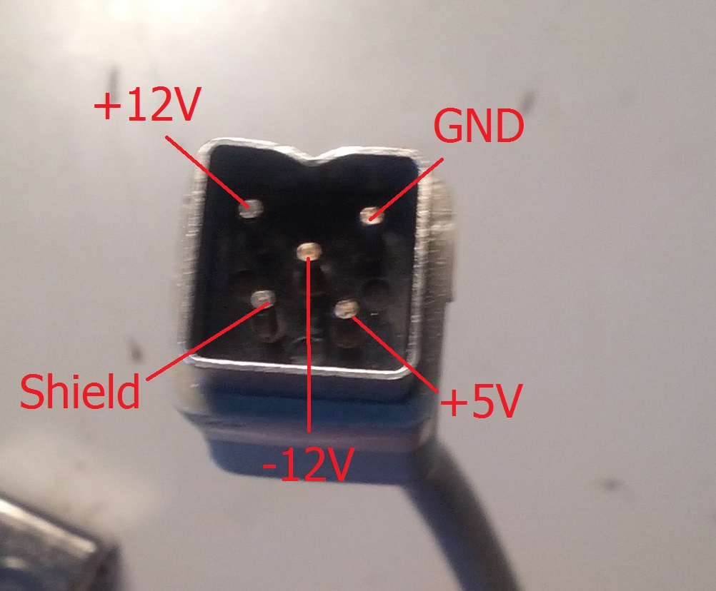
|
|
|
|
04 May 2024, 21:33
|
#7 |
|
Registered User
Join Date: Jun 2010
Location: PL?
Posts: 2,810
|
Use continuity tester in your multimeter - in real life shield may be more trickier than just plain GND connection on both sides - sometimes shield is grounded only on one side.
But i agree with Daedalus - it should be not critical if GND hooked properly. |
|
|
|
05 May 2024, 00:47
|
#8 |
|
Registered User
Join Date: Oct 2007
Location: ManCave, Canada
Posts: 1,615
|
ok so I got it narrowed down to 2 wires-green & yellow.
in resistance mode: when I touch shield pin with green wire get 0L on meter green with ground get numbers jumping around yellow with shield get numbers jumping around yellow with ground get 0L so now I'm confused which of the two is SHIELD ??? btw with load on I'm getting 12.18V, 5.09V, and -11.49V from my ATX PSU...is the -12V line being low an issue? |
|
|
|
05 May 2024, 17:15
|
#9 |
|
Registered User
Join Date: Jun 2012
Location: Toronto / Canada
Posts: 237
|
the -12V line is acceptable at -11.49v generally a +/- 12v line is acceptable at a +/- 1v tolerance and a +5V line is acceptable at a +/- 0.5v tolerance.
|
|
|
|
05 May 2024, 21:21
|
#10 |
|
Registered User
Join Date: Jun 2009
Location: Dublin, then Glasgow
Posts: 6,369
|
Numbers jumping around might be as simple as the connection between the probes and the pins or wires not being great. Do you get zero when you touch the probes together?
That being the case, it looks like yellow is the shield and green is ground. As for the voltages, the +/- 12V rails are less critical. The 5V rail is, and I would say +/-0.5V is too wide - generally, TTL logic (as is used by much of the Amiga circuitry) is specced for +/-5%, or +/-0.25V. If your 5V rail was as low as 4.5V I'd expect all sorts of problems, and possibly a non-booting machine. Bear in mind though that checking voltages without any load can be misleading. You might find they shift a bit once connected to the machine. |
|
|
|
05 May 2024, 23:57
|
#11 | |
|
Registered User
Join Date: Oct 2007
Location: ManCave, Canada
Posts: 1,615
|
Quote:
Thanks again  Last question, is it better to connect the SHIELD pin with the yellow wire from the ATC cord or to use a separate wire attached to the tower case From AmigaKits website they say: "Trim back the plastic sheath of the five individual wires (+12v, +5v, Ground, Shield and -12v) in the power cord to expose 5mm of copper strands. ? Insert them into corresponding wire holes in the terminal block as marked on the adapter. Ensure no copper is exposed and each copper strand is fully inserted into the hole." Last edited by klx300r; 06 May 2024 at 00:21. |
|
|
|
|
06 May 2024, 11:06
|
#12 |
|
Registered User
Join Date: Jun 2009
Location: Dublin, then Glasgow
Posts: 6,369
|
If you're putting it in a tower case then you shouldn't really need to worry about the shield at all - the motherboard should be grounded to the case directly by whatever brackets or mounts are being used.
Last edited by Daedalus; 06 May 2024 at 21:22. |
|
|
|
06 May 2024, 16:16
|
#13 |
|
Registered User
Join Date: Oct 2007
Location: ManCave, Canada
Posts: 1,615
|
@ Daedalus
Thanks for clearing things up for me
|
|
|
| Currently Active Users Viewing This Thread: 1 (0 members and 1 guests) | |
| Thread Tools | |
 Similar Threads
|
||||
| Thread | Thread Starter | Forum | Replies | Last Post |
| ATX to A5/6/1200 Adapter | pngcan | Hardware mods | 3 | 18 February 2022 13:42 |
| Atx to AT 8 pin adapter? | livewirerocks | support.Hardware | 6 | 29 August 2019 11:39 |
| Custom power adapter for ATX | doufas | Hardware mods | 19 | 05 March 2014 00:41 |
| A2000 A2386SX BridgeBoard & ATX-PSU Adapter | amigoun | support.Hardware | 9 | 08 April 2013 23:16 |
| Swap: ATX adapter for buffered interface | scrappysphinx | MarketPlace | 0 | 16 June 2010 16:05 |
|
|


