
|
 25 February 2015, 10:57
|
#21 | ||
|
Glastonbridge Software
Join Date: Jan 2012
Location: Edinburgh/Scotland
Posts: 2,243
|
Quote:
Quote:
It is easy enough to sort all the objects by Z-distance first, then one can multiply the points of the next object by the rotation matrix and calculate screen co-ordinates, while the previous object is still being drawn. |
||

|
|
25 February 2015, 19:36
|
#22 | ||
|
Registered User
Join Date: Jan 2012
Location: USA
Posts: 372
|
Quote:
Quote:
And there typically are plenty of other calculations that must be done in a program like Elite. It isn't all rotation matrix calculations. It would be desirable to overlap rendering with all those other calculations, too. Here's what I would try if I had the skills: The Amiga hardware permits the copper to run a list that programs the blitter. I'd use the copper for most of the rendering. With some cleverness, it's possible to get the copper to cross vblanks without misprogramming the blitter allowing for CPU/blitter concurrency. Of course the CPU has to reprogram bitplane pointers at some point before the top of the display using an interrupt (VBlank or even timer based on HSync), but getting CPU/blitter concurrency is probably more than worth it. There's even an opportunity to use the blitter together with CPU for occlusion culling by using BZero together with an occlusion mask. Going all out, one could even use a tile-based (16x16 pixels) system together with occlusion culling to minimize the amount of rendering done by the blitter of scenes that have large polys obscuring most of the background polys. The render pipeline (running concurrent with calculations for the next frame) would look something like: Clear poly buffer (will hold multiple single bitplane filled polys) Clear occlusion buffer to all 1s (zeroed areas will indicate an area covered by a poly) Clear render buffer Draw polys/fill to multiple poly buffer (holds multiple single plane filled polys) Sort polys front to back Occlusion cull by using AB blit with D=A*B (test to see if new poly would add to scene) and draw black (zeroed) single bitplane polys to occlusion buffer if BZero is nonzero (to reduce unnecessary blits to frame buffer) Sort non-occluded polys back to front Render tiles of non-occluded polys using LF to proper plane for correct color The key to making this fast is to allow the CPU to calculate a frame ahead while much of the blitting is done concurrently. The CPU would have to be diverted to help with occlusion culling and sorting from time to time, but most of the other blits can be done with copper lists. It the CPU is allowed to begin calculating one frame ahead, a great deal of concurrency can be taken advantage of. For instance, once a copper list is built to clear buffers and draw lines/fill polys in the poly buffer, the CPU can immediately move to calculating the coordinates of next set of polys for the next frame and building the next copper list while the previous copper list is rendering. It's all a great deal of work, and while the additional rendering steps would tend to make for slower rendering of scenes with very few polys, as the number of polys grows, the scheme should quickly overtake simpler methods I think. The idea is to make fast cases that have many polys. Occlusion culling might even make 640x400 8-colors usable. |
||
|
|
|
25 February 2015, 21:10
|
#23 | |
|
Glastonbridge Software
Join Date: Jan 2012
Location: Edinburgh/Scotland
Posts: 2,243
|
Quote:
If you don't see how filling several polygons at one is quicker than filling them all separately and then separately copying them into the destination then i don't know what to say. On a single object, polygons will overlap significantly along the edges, and for smaller objects this is ever more the case. You can also "cancel out" shared edges before you even draw them. You can of course have as many planes as you like in the destination buffer. Just using minterms, you can have a 3 colour object copy to a 32 colour screen with colours remapped anywhere into the destination. Also you can draw the first object to be drawn directly onto the screen, and dynamically re-order the palette. If this object is a concave interior, you can have as many colours as you like and fill the whole thing in one pass. Last edited by Mrs Beanbag; 25 February 2015 at 21:23. |
|
|
|
|
26 February 2015, 06:08
|
#24 | |
|
Registered User
Join Date: Jan 2012
Location: USA
Posts: 372
|
Quote:
What I'm talking about is first drawing one filled single bitplane polygon of a larger object in a buffer. Then by using that single bitplane polygon, write zeros or ones as appropriate directly onto the bitplanes of next frame to be displayed (as in a double buffered scheme) by setting the correct LF for each plane to set the color. There's no extra destination or separate area where an object is built and then blitted into the scene. Each polygon of the object is written directly onto the next image that will be displayed. After all the polygons of all the objects have been drawn, a simple change of bitplane pointers is enough to display the new frame. If the polygons are simply drawn back to front, then there's no need for hidden surface removal and there's no need to restrict one's self to convex polyhedra or to objects that have no holes. Now maybe I misunderstand you, but as far as I can tell, you advocate for drawing the boundaries of several polygons of an object, taking care not to draw the lines of hidden facets, filling them all at once to draw a complete object, then blitting that whole object into the next frame to be displayed along with other objects. Is that the case? I'm curious, then, how do you quickly determine which facets are hidden on a non-regular polyhedron? The method I'm familiar with involves computing surface normal vectors. |
|
|
|
|
26 February 2015, 11:48
|
#25 | |||
|
Glastonbridge Software
Join Date: Jan 2012
Location: Edinburgh/Scotland
Posts: 2,243
|
Quote:
Quote:
So you can render three or more polygons with only two fills and one copy per bitplane of destination screen. This buffer need not be cleared afterwards, because we can use a separate buffer to render the lines and just clear that by going over the lines a second time. Each line will only need drawing exactly twice, with shared edges eliminated. Consider a simple cube. When seen from some angle where any 3 sides are visible, the bounding boxes of these sides will significantly overlap. Doing 3 slightly smaller fills/copies won't be as fast as doing 2 fills and 1 copy. Quote:
Objects with holes don't cause a problem, neither do completely concave objects. For instance one could render a cube with a tunnel through by rendering the tunnel and then rendering the cube with holes in. One can also set any of the sub-object colours to transparent and effectively use one of the source bitplanes as a mask, so you can render concave features onto things AFTER drawing them. You can also use non-convex/concave objects to do weird effects since overlapping polygons will XOR with each other, as well as 2-colour surface decals. Here is an illustration showing the potential overlap of polygon bounding boxes on a rotated cube: 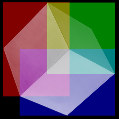 The overlap could be even more when we consider we have to snap to word boundaries. Last edited by Mrs Beanbag; 26 February 2015 at 12:11. Reason: added illustration |
|||
|
|
|
01 March 2015, 21:04
|
#26 |
|
Registered User
Join Date: Jan 2012
Location: USA
Posts: 372
|
Thanks for your thoughts, Beany. Appreciated. But by my math, your cube example actually argues for doing three single-bitplane fills.
Doing three separate one-bitplane fills I get: 14 words x 316 lines = 4424 words filled (red area) 15 words x 241 lines = 3615 words filled (green area) 15 words x 243 lines = 4460 words filled (blue area) Total words to be filled = 12499 Total DMA cycles for fill = 12499*3 = 37497 DMA cycles For a five plane display, cutting each polygon into the new frame with ACD blit = 3 x 5 x 12499 = 187485 DMA cycles. Total DMA cycles = 224982 Filling two planes with all three cube faces to be filled all at once: 25 words x 400 lines x 2 planes = 20000 words to be filled. Total DMA cycles for fill = 60000 DMA cycles ABCD blit into a five plane frame = 4 x 5 x 10000 = 200000 DMA cycles. Total DMA cycles = 260000 Perhaps the better method is simply very dependent on the pattern of the polygons that make up the object. For filling, the cube provides too much empty area that must unnecessarily be touched. Some other shape might be faster (a polyhedron with tessellated faces and few colors perhaps?) The ABCD blit is a nice trick, but it too requires that the blitter touch much empty space in the case of the cube. Again, which is better must be object dependent. With respect to calculating away hidden surfaces, using the debugger to examine several 3d poly games running on an emulated A500 and looking at the ratio of time used for calculation versus polygon draw, I can say, except for demos with a very small number of objects, that the ratio of calculation time to polygon fill/render time is usually greater than 1:1. In larger worlds, many calculations are done that result in nothing being drawn. Many polygons are clipped away or are located behind the viewer. This suggests that it might be better to use the blitter to cover more distant polys than to introduce additional calculation for hidden surface removal, provided the CPU and blitter can be made to run concurrently. |
|
|
|
01 March 2015, 21:32
|
#27 |
|
Glastonbridge Software
Join Date: Jan 2012
Location: Edinburgh/Scotland
Posts: 2,243
|
i feel like you have cheated me a little here since the area to fill is only 24 words x 380 lines x 2 planes = 18240, or 54720 fill cycles + 182400 copy cycles = 237120 in total. So i get your point but it is a closer call than you thought.
Also one need not necessarily fill the entirety of the bounding box for both planes (for instance one plane only contains faces A and B while the other only contains B and C) and it saves having to draw some lines twice. But as you say it depends on the object, a cube is a simple example but imagine an object that has many triangles in the same colour, like a 2 or 3 colour boing ball. You always have to calculate which polygons are behind the viewer, you can't draw those in any case. There are also many calculations that you have to do per-polygon whether they are visible in the final scene or not. But if you are not doing hidden surface removal, how do you order the polygons? Simple Z-sorting is not enough for something like an L-shaped object, for example. Whereas with hidden surface removal one can often use a fixed drawing order. When polygons are very distant it might be quicker to fill them than to do a couple of multiplies required for testing visibility, but we have to do some multiplies anyway to calculate the screen co-ordinates of all the points. EDIT: also consider the fill operation includes an idle cycle, which can be used by CPU. Last edited by Mrs Beanbag; 01 March 2015 at 22:04. |
|
|
|
02 March 2015, 05:57
|
#28 | ||||
|
Registered User
Join Date: Jan 2012
Location: USA
Posts: 372
|
Quote:
 Quote:
Quote:
|
||||
|
|
|
02 March 2015, 11:58
|
#29 | ||
|
Glastonbridge Software
Join Date: Jan 2012
Location: Edinburgh/Scotland
Posts: 2,243
|
Quote:
We need to calculate a predicate based on a vector triple product of the triangle vertices (assuming we are working with triangles, but any face visibility can be calculated from any co-planar triangle). P = (Ay.Bz - Az.By).Cx + (Az.Bx - Ax.Bz).Cy + (Ax.By - Ay.Bx).Cz [1] = Ay.Bz.Cx - Az.By.Cx + Az.Bx.Cy - Ax.Bz.Cy + (Ax.By - Ay.Bx).Cz [2] = (Bx.Cy - By.Cx).Az + (Ay.Cx - Ax.Cy).Bz + (Ax.By - Ay.Bx).Cz [3] = {(Bx.Cy - By.Cx)/(Bz.Cz) + (Ay.Cx - Ax.Cy)/(Az.Cz) + (Ax.By - Ay.Bx)/(Az.Bz)}.(Az.Bz.Cz) [4] but we already did Ax/Az, Ay/Az &c because these are just the screen co-ordinates of the points! so let ax = Ax/Az... and we don't care about multiplying by (Az.Bz.Cz) at all because we only want the sign of the result, not the magnitude! So assuming all of these are positive (but we can just use XOR otherwise)... p = bx.cy - by.cx + ay.cx - ax.cy + ax.by - ay.bx [5] = (ax-cx)(by-cy) - (ay-cy)(bx-cx) [6] Sign(P) = Sign(p) xor Sign(Az) xor Sign(Bz) xor Sign(Cz) [7] This is only two multiplications and it is good as long as none of the Z co-ordinates are zero (in which case we can't really compute the screen co-ordinates - but it simplifies [3] for us). Quote:
Consider the following shape: 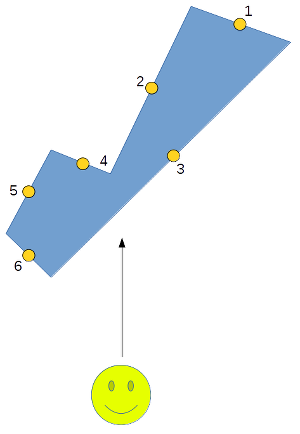 The sides of the polygon are "walls" from the perspective of the viewer at the bottom. Sorted by their centre point, we can see that faces 4 and 5 get incorrectly drawn over the top of face 3. Last edited by Mrs Beanbag; 02 March 2015 at 12:25. |
||
|
|
|
02 March 2015, 21:59
|
#30 |
|
Registered User
Join Date: Jan 2012
Location: USA
Posts: 372
|
Excellent, Bean! Thanks!
|
|
|
|
02 March 2015, 22:45
|
#31 |
|
Glastonbridge Software
Join Date: Jan 2012
Location: Edinburgh/Scotland
Posts: 2,243
|
of course the other way to do it is to pre-calculate all the normals in the object's co-ordinate system, and instead of rotating the normals, transform the camera position by the inverse object transform, and then use that for dot products. That's only 3 multiplies. You can use that also to do light source shading. Rotate the light source instead of the normals, which is one rotation per object and a dot product per face.
As for Z-sorting for the draw order of the objects, it might be better to sort by distance (or distance squared) and then do some smooth sort such as insertion sort, which has to do less work the fewer objects change order from one frame to the next (best case O(n)). That way, just spinning the camera round won't lead to any change in the ordering, and as long as object and camera motion is fairly sensible, the draw order won't radically change from one frame to the next so the sorting should stay near-linear. |
|
|
|
21 August 2015, 04:38
|
#32 | ||
|
Code Kitten
Join Date: Aug 2015
Location: Montreal/Canadia
Age: 52
Posts: 1,178
|
Quote:
The visibility list for a 16 faces object would be fetched in a single access. If an object has a complex geometry, just split it up until the parts can be reasoned about in the same way. Remember the golden rule: "the fastest computation is the one you don't perform".  Quote:
Clustering objects by proximity allows to reduce the range on which to apply sorting: sort the groups by Z squared, then inside each group sort the objects. Best case stays at O(n), but worst and average cases become much better. You can also avoid sorting if you have higher level knowledge about object trajectories: if two objects move at constant speed the moment they reach equal Z can be computed in advance. It's a very specific and unlikely example but you get the idea: take one step back to see the bigger picture and you can remove a lot of work. A bit more on-topic: lately I have been thinking about reducing blitter bandwidth when blitting polygons and Mrs Beanbag's suggestion to reorder the palette struck a chord. It seems possible to reduce the number of bitplanes to draw by subdividing the screen in horizontal sections, each section with a roughly constant number of colors drawn. Areas with only a few colors drawn can have their palette reordered by the copper to blit on the minimum number of bitplanes possible. This is not Amiga specific per se but the copper makes this extremely low overhead. I haven't gotten into detailing the needed computations but I would say that this is at least worth considering. |
||
|
|
|
16 January 2018, 18:39
|
#33 |
|
Registered User
Join Date: Feb 2009
Location: london/england
Posts: 1,347
|
You both lost me at 'area fill' lol this is way above my head!
The thing that interests me about the blitter to fill the triangles/areas is that to write a Rescue on Fractalus type mountain rendering routine on a 7mhz 68000 would be trivial and lightning fast. If the large areas were filled by the blitter while the 68000 gets on with doing more accurate/complex iterations than were possible on the Atari 800 computers. The intro to Master Blazer by Rainbow Arts has a really hacky implementation of the Rescue on Fractalus engine and left me very underwhelmed. If I even understood half of what Scali was going on about (what an unhelpful twat he is too btw) I would try this out because Rescue on Fractalus is the finest 8 bit game ever coded, certainly better than any 2D rubbish on the NES the yanks go on and on and on about 3D is not my thing at all, I can just about do bitplane masking but 3D matrices....hmmm....might need to go back to school and do A-level maths! |
|
|
|
19 January 2018, 23:23
|
#34 |
|
Code Kitten
Join Date: Aug 2015
Location: Montreal/Canadia
Age: 52
Posts: 1,178
|
It looks like the Blitter fill mode could indeed be leveraged to help in fractal like rendering but the topic is quite distinct from 3D polygon filling and would deserve its own thread.
You would also get more precise and appropriate feedback in such a thread. Also, this thread still has potential for future discussions. Knowing them, I would presume that neither mc6809e nor MrsBeanbag have reached the end of it yet.
|
|
|
|
25 January 2018, 15:30
|
#35 |
|
Moderator
Join Date: Nov 2004
Location: Eksjö / Sweden
Posts: 5,650
|
You don't need to store normals with the objects, though it's equivalent to calculating the normal.
The important thing is that the normals are calculated from perspective-transformed coordinates, anything else is incorrect for visibility/light sourcing and you will get glitches and scratch your head needlessly.
|
|
|
| Currently Active Users Viewing This Thread: 1 (0 members and 1 guests) | |
| Thread Tools | |
 Similar Threads
|
||||
| Thread | Thread Starter | Forum | Replies | Last Post |
| Blitter poly-line draw & filling - the 100th | Herpes | Coders. Asm / Hardware | 12 | 14 May 2014 01:34 |
| CPU Filling vs. Blitter Filling Routine | victim | Coders. General | 18 | 26 January 2014 02:15 |
| Blitter filling routine used in games | Codetapper | Coders. General | 2 | 26 January 2012 10:20 |
| Filling with the blitter... | Lonewolf10 | Coders. Tutorials | 7 | 13 September 2011 14:30 |
| Would you like some polygons? | Dalai | Retrogaming General Discussion | 7 | 05 October 2004 00:20 |
|
|


