
|
 08 May 2017, 23:09
|
#21 |
|
Registered User
Join Date: Jun 2012
Location: Worksop/UK
Age: 59
Posts: 1,328
|
Use a Goliath myself, excellent PSU. Hard to find now though. The best "new" options are already mentioned except a ATX converted PSU which can be purchased at most Amiga stores.
|

|
|
09 May 2017, 01:38
|
#22 |
|
Registered User
Join Date: Feb 2008
Location: Brussels / Belgium
Age: 46
Posts: 55
|
Thank you for all the help. I understand that a PSU is hard to predict as long as you don't know what it is really made of.
I have read that for the Commodore 64 there is an adapter you connect between the PSU and the computer that protects the computer by cutting the power off in case of excessive voltage. Is there anything similar for the Amiga? I have found this other informative thread about "killer power supplies". Can you confirm that I should only test a PSU after adding a dummy load on the +5V and +12V pins, in order to get correct measurements, and protect the PSU from breaking down if it is old or bad quality? |
|
|
|
09 May 2017, 02:25
|
#23 |
|
Registered User
Join Date: Jun 2012
Location: Worksop/UK
Age: 59
Posts: 1,328
|
Most PSU's (of the newer type especially) require a load on them anyway to get a accurate reading, without a load you would get very inaccurate results.
Some switch mode types won't even give out any voltage without a load on them and turn themselves off, Amiga PSU's don't do this but could give a false reading without a load on them. |
|
|
|
09 May 2017, 08:23
|
#24 |
|
Registered User
Join Date: Sep 2007
Location: Stockholm
Posts: 4,332
|
The C64 "saver" box was made because the +5V regulator of the C64 PSU often fails in a spectacular way, killing the C64. This has yet to be documented on the Amiga, which uses totally different designs for its PSUs.
|
|
|
|
09 May 2017, 09:57
|
#25 | |
|
Registered User
Join Date: Jun 2009
Location: Dublin, then Glasgow
Posts: 6,334
|
Quote:
|
|
|
|
|
09 May 2017, 14:29
|
#26 |
|
Registered User
Join Date: Feb 2013
Location: Argentina
Posts: 281
|
Hi.
To test a PSU, it must have a load. You can assemble this circuit to generate a load. http://eab.abime.net/showthread.php?t=70016 When the circuit is connected to the PSU, measure the voltages. It is advisable to change the electrolytic capacitors of the PSU. |
|
|
|
09 May 2017, 18:15
|
#27 | |||||
|
Banned
Join Date: Dec 2016
Location: Nottingham, UK
Posts: 481
|
Quote:
The chances of actually damaging an A500, A600, or A1200 is less than 1 in a 100 though. This becomes zero if you just test the PSU voltages first, with a multimeter. Quote:
http://ianstedman.co.uk/Amiga/amiga_..._supplies.html This is a more general article on using a multimeter to measure voltage. https://learn.sparkfun.com/tutorials...-a-multimeter/ Here's a video if you are really struggling. http://r.duckduckgo.com/l/?kh=-1&udd...%3DZBbgiBU96mM Quote:
Quote:
This last point I could well be wrong on, maybe I've been looking in the wrong places for 30 years. Quote:
I usually stick to AC mains earth pin rather than ground for shields. This isn't always an option, and can produce problems with analog systems like audio, video displays, serial and parallel connections, etc. 9/10 time it makes no difference, I'll admit. Last edited by Pat the Cat; 09 May 2017 at 18:21. |
|||||
|
|
|
09 May 2017, 21:09
|
#28 | |||
|
Registered User
Join Date: Jun 2009
Location: Dublin, then Glasgow
Posts: 6,334
|
Quote:
Quote:
Quote:
|
|||
|
|
|
09 May 2017, 23:21
|
#29 | |
|
Registered User
Join Date: Feb 2017
Location: Ireland
Posts: 752
|
Is this the perfect replacement PSU for the Amiga voltage-wise and would there any wiring guide?
Quote:
|
|
|
|
|
10 May 2017, 00:09
|
#30 | |
|
Registered User
Join Date: Jul 2013
Location: Finland
Posts: 24
|
Quote:
There was no need for a wiring guide because all the wires were clearly labeled on the original power brick PCB. |
|
|
|
|
10 May 2017, 00:59
|
#31 | |
|
Registered User
Join Date: Jun 2009
Location: Dublin, then Glasgow
Posts: 6,334
|
Quote:
|
|
|
|
|
10 May 2017, 02:05
|
#32 |
|
Registered User
Join Date: Feb 2008
Location: Brussels / Belgium
Age: 46
Posts: 55
|
Thank you everyone for your valuable help!
Can you confirm that testing an original Amiga PSU without load will not damage it? Setting up a dummy load is beyond my capabilites at present, so I will begin by measuring without load, even if it produces inaccurate results. Even using a multimeter is new for me! But according to what I have read, my 20-year-old internal PC PSU modified with an Amiga connector might be old or cheap enough to suffer from being tested without load, so I will probably look for nearby help. |
|
|
|
10 May 2017, 04:41
|
#33 |
|
Registered User
Join Date: Jun 2013
Location: Australia
Posts: 685
|
Here’s an example of measuring a linear supply, in this case a CD32, with a cheap multimeter.
It’s easier than you think. For switchmode, it will be the same once the supply is loaded down. [ Show youtube player ] There is some inaccuracy in the meter itself, and due to added cable length, temperature etc. but this is acceptable. Also for linear supplies the meter should become stable, and not jump around too much (power supply ripple). Now this Pico PSU thing... Does anyone have one of these that could tell me the two chips on it? And verify the yellow parts are just covered ferrite inductors? 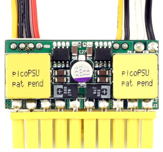 Because what I suspect is the two duplicate regulator circuits are more or less example schematics from the chip manufacturer, and at best they trademark their name, and have copyright on their PCB artwork, but the patent pending part is a joke. That kind of thing motivates me to reproduce and publish the full schematic, and also email it to them from my ISP. |
|
|
|
10 May 2017, 09:59
|
#34 |
|
Registered User
Join Date: Jun 2009
Location: Dublin, then Glasgow
Posts: 6,334
|
I'm not sure what your ultimate goal is there... I have a couple of them, and from memory they are inductors but I'm not going pulling them out of where they are to read the chip numbers. There are already plenty of (poorly executed) clones around if your issue is with the company themselves. Just bear in mind that there are two double-sided PCBs back-to-back, so there are a lot more parts involved than you can see in that image. If you were going to reproduce the schematic, you'd really want to get your hands on one yourself and do a full stripdown to identify all the components used. Most PSUs are based on pretty standard schematics anyway, it makes perfect sense to start with the manufacturer's application notes.
Patent Pending means just that - it's pending. It hasn't been granted yet, and doesn't do anything to affect its chances of being granted. Nothing wrong with that. But if you can get hours of enjoyment from going on a little crusade, then by all means. |
|
|
|
10 May 2017, 12:34
|
#35 |
|
Registered User
Join Date: Jun 2013
Location: Australia
Posts: 685
|
It’s the “Patent Pending” that gets on my nerves if indeed it’s just the regulator chip manufacturer’s example, and no new IP.
That would be close enough tot see from a data sheet.. a half hour job at best, not a crusade. |
|
|
|
10 May 2017, 12:59
|
#36 | |
|
Registered User
Join Date: Sep 2007
Location: Stockholm
Posts: 4,332
|
Quote:
|
|
|
|
|
10 May 2017, 13:33
|
#37 |
|
Registered User
Join Date: Jun 2013
Location: Australia
Posts: 685
|
Because the “Pat Pend” is only there to imply there is some IP to be protected,
which is fair enough if there is, but I seriously doubt it. For the initial first year patent, little if anything of IP has to be demonstrated, and it’s also very cheap, but there’s also no reason I see to apply for it at all, other than to discourage others from making or open sourcing the same thing, which again, is fair enough if there’s something unique about it, but again, I doubt it. |
|
|
|
10 May 2017, 14:50
|
#38 |
|
Registered User
Join Date: Jun 2009
Location: Dublin, then Glasgow
Posts: 6,334
|
It's getting a little off-topic here, but without having looked at the patent application you can't know what they believe is novel. It probably isn't the use of standard circuit designs that's novel enough to warrant a submission, and if that's what it's about, there's an abundance of prior art so it'll never be granted. I'd suspect it's more about the form factor, which may not have been done before. But that's up to the respective patent offices to decide upon. Companies submit patent applications all the time for almost anything they develop in house, and while they try to maximise their chances of having them granted by making sure their concept is unique, it's accepted that a certain proportion will always be rejected, and rightly so in most cases.
|
|
|
|
11 May 2017, 08:52
|
#39 | |
|
Registered User
Join Date: Feb 2008
Location: Brussels / Belgium
Age: 46
Posts: 55
|
Quote:
|
|
|
|
|
15 May 2017, 18:34
|
#40 |
|
Registered User
Join Date: Feb 2017
Location: Ireland
Posts: 752
|
Just performed a voltage test on one of my PSUs and I'm getting 9.3v on the +12v rail. Should I be concerned?
|
|
|
| Currently Active Users Viewing This Thread: 1 (0 members and 1 guests) | |
| Thread Tools | |
 Similar Threads
|
||||
| Thread | Thread Starter | Forum | Replies | Last Post |
| Developing a new A500/1200/600 power supply. -12V needed? | Mounty | Retrogaming General Discussion | 114 | 03 August 2016 17:16 |
| New Amiga 500/600/1200 HD power supply | mech | MarketPlace | 11 | 28 December 2010 22:05 |
| WTB: A500 power supply or A1200 power supply (USA model) | CMA Death Adder | MarketPlace | 7 | 01 October 2010 15:10 |
| Power Supply for 600/1200 | stulec52 | MarketPlace | 1 | 22 June 2009 14:26 |
| Amiga 1200 UK-US Power Supply Questions..... | batfatty | New to Emulation or Amiga scene | 11 | 04 December 2008 21:34 |
|
|


