
|
 08 September 2009, 00:34
|
#1 |
|
Registered User
Join Date: Jan 2008
Location: United Kingdom
Age: 46
Posts: 733
|
Stedy's RGB to SCART cable
Hi
Just what we want, another thread on RGB to SCART cables.  All details in this post and any relevant comments will be used to create an article on my website in due course. I'm a bit busy at the moment so updating the website is a low priority. This cable has been tested with multiple LCD and CRT TVs. Before explaining the differences, time for the diagram.  Before creating this cable I undertook a number of measurements on the Amiga video outputs. The first issue I noticed was the voltage on the SYNC signal, it was 4.8V peak to peak. Modern TVs have video decoder devices, their job is to decode the analogue video waveform into a digital video format, for SDTV this is usually a BT.656 video stream with a YCrCb colur space. Point aside, these devices take the composite video input or sync on green and process the signal to extract sync timing. They expect a 1V peak to peak signal, connecting the CSYNC signal from the Amiga could harm the device, especially as most parts run from 3.3/1.8V supplies. Video decoders are used in CRT and LCD TVs. As the composite sync input has a 75 ohm terminator, adding 330 ohms, in series with the 47 ohms inside the Amiga has the effect of reducing this signal to less than 1V. As an option, you can use the CVBS signal from the Amiga. For my testing purposes, I had both connected via a switch. The BLANK signal (pin 16 of the SCART) is fed from +5V via a 75 ohm resistor, which together with the 75 ohm terminator in the TV, creates a voltage of 2.5V, adequate to RGB input mode. The AV mode signal (pin 8 of SCART) is fed +12V via a 1K resistor. The resistor is present to limit the current in case of a short circuit. Pin 18 of the SCART lead (blanking ground) was connected to pin 13 of the Amiga (digital ground). Each video signal had an appropriate ground signal. I did not connect the SCART shield, pin 21. My £1 cable, which was cut up to make this, was not fully shielded so there was no point. So after making the cable it was time to test it. Pluged it into the Amiga and the TV, switched TV, then Amiga. The TV selected AV1, so the SWITCH signal was working but I had a black screen. Fired up the oscilloscope and looked at the CSYNC signal There were 2 sync signals present. Switched the Amiga off and I saw a nice composite video signal! In my cheap SCART cable, pins 19 (Video Out) and 20 (Video In) had been swapped over in the cable. So connecting pin 20 at the TV end to the CSYNC signal of the Amiga and it worked. The picture was nice and clear, here is Directory opus  Colour bars  Oh and my test setup  The only issue I did notice, was that the LCD showed up the anti-aliased fonts of the Amiga. This is to be expected and I have seen similar effects when using old equipment with LCDs. Now that I had a stable setup I set about injecting faults to see what happens. The first test was to disconnect the blank signal (pin 16 of the SCART) The display went black. If I switched the CSYNC source from the TTL CSYNC of the Amiga, to the Composite video output of the Amiga, I had an image, albeit a crap one!  Does the composite video output normally look this crap? The next test was to change the voltage on the SWITCH (pin 8 of SCART) 9-12V = RGB, 4:3 aspect ratio 3-7V = RGB 16:9 aspect ratio 0-2V = TV So when making a cable, ensure you have 9-12V at pin 8 of the SCART lead and that the blank signal is 1-3V. To test the interchangeability of my cable, I tried another LCD TV, this time a cheap Akura set. This system had trouble synchronising to the composite video signal from the Amiga but worked fine with the reduced TTL CSYNC signal. It incorrectly detected the video as NTSC when fed from the composite video output! Loss of CSYNC, from any source, lead to a black screen. The final test was to use a Ferguson CRT TV. This worked fine when fed a CSYNC signal from the composite output or the modified TTL CSYNC signal. If the CSYNC signal was removed, the picture rolled diagonally. In all tests the colours were well defined and I used colour bars, multiburst and convergence test patterns to confirm the display quality. When I write this up for my website, I will add more test picture some oscilloscope plots and the rationale behind it. Before I do this, some feedback is required from you, the reader. 1) Have you tried this cable and did it work? 2) Did you try it with CRT and LCD displays? Purchasing cables I do not make these cables for sale but the great guys at AmigaKit do. http://amigakit.leamancomputing.com/...roducts_id=226 and http://amigakit.leamancomputing.com/...roducts_id=778 are the best cables on the market and have been tested with a wide variety of LCD TVs. Beware of cheaper cables that only work with CRT TVs. That's all folks Ian Last edited by Stedy; 04 June 2021 at 18:28. Reason: Fixing broken links |

|
|
08 September 2009, 01:22
|
#2 |
|
Ya' like it Retr0?
Join Date: Jul 2005
Location: United Kingdom
Age: 49
Posts: 9,768
|
Thanks Stedy
I will give this a build this week and let you know =) I think I have the most fussiest of Plasma RGB in TV sets... I have tried so many different methods of configuring SCART for the Amiga output it is crazt, what really peeves me is that it would work fine on the CRT tv, just not my plasma!!! So it would be nice to be able to put this to bed to be honest! |
|
|
|
08 September 2009, 12:50
|
#3 |
|
Novice in the Black Arts
Join Date: Nov 2004
Location: Kingston upon Hull
Age: 47
Posts: 263
|
@Stedy
Good comprehensive guide! I have the following comments/observations: I have no resistance between 10 (Amiga) and 20 (SCART) and have had no ill effects (thus far). Also, I have nothing connected to pin 18 of the SCART with no ill effects. As with yourself, I used a similar (80 Ohm) resistance between pin 23 (Amiga) and 16 (SCART), although I'd recommend testing the resistance under load for any particular TV between pin 16 and ground on the SCART socket to obtain the correct resistance to insert between 23 (Amiga) - 16 (SCART). The resistor you solder in between +5V out on the RGB port, and pin16 of the SCART should be NO LESS THAN 0.7 x measured resistance measured between pin16 - ground, and no greater than 2.5 x measured resistance to achieve the 1.4V - 3V required by the RGB sense circuit on pin 16. Additionally, your colour grounds for blue and red appear to be crossed: Should be (Amiga - SCART): 16-13, 17-9, 18-5, although this shouldn't make the slightest difference as colour grounds tend to be common, or have identical term resistance in my experience. I guess from the 1K resistance between 22 (Amiga) - 8 (SCART) that pin 8 of SCART has a high resistance termination? One final point to note - audio in/out and video in/out are always crossed on SCART cables (in my experience). Audio/video output at end #1 of a SCART-SCART cable will always connect to video in at end #2 for obvious reasons. Fooled me the first time I made my cable up though... Excellent presentation, and really good info on the effects of changing/removing connections - should help a lot of people in troubleshooting their homebrew cables! :-) |
|
|
|
08 September 2009, 12:51
|
#4 | |
|
Novice in the Black Arts
Join Date: Nov 2004
Location: Kingston upon Hull
Age: 47
Posts: 263
|
Quote:
@Z - I thought you'd identified that your plasma would only accept S-Video input (not RGB) through that particular SCART socket? It was a long while ago though... |
|
|
|
|
08 September 2009, 14:53
|
#5 | ||
|
Thalion Webshrine
Join Date: Jan 2004
Location: Oxford
Posts: 14,330
|
Quote:
Quote:
Last edited by alexh; 08 September 2009 at 15:10. |
||
|
|
|
08 September 2009, 14:57
|
#6 |
|
Ya' like it Retr0?
Join Date: Jul 2005
Location: United Kingdom
Age: 49
Posts: 9,768
|
@Booty,
long time no see on the boards, I do hope this changes my friend! Now the Hitachi Panel I have has 3 SCART sockets SCART 1 = RGB SCART 2 = RGB SCART 3 = NOT RGB (with this you can set one of the SCART's as an Output to Controll the VCR or something like that) The Hitachi panel also has 1 SVideo In 1 HDMI 1 VGA 1 Component 1 RCA Composhite IN 1 RF In (analog not digital) the component runs to a 3 way crunch box (for Xbox / Ps2 / spare) the HDMI runs to my Media PC the VGA runs to the filestore but essentially spare for testing and setiing up pc's etc RGB 1 SCART - not in use RGB 2 SCART - SKY 3 SCART spare - testing consoles etc SVideo In - Amiga Svideo (from Amiga Mainiac =)) RCA - Composite (Composhite) not used RF In - Not used the RGB SCART 1/2 work with the Dreamcast and XBOX RGB Cable (its not composhite) Composhite input (by scart or by direct input) looks absolutely dreadful! with the exception of 1 device I tried, it artifaces, blurs specificaly on STILL pictures, oh its horrid. the Device I tried is infact the Amiga-Svideo *composite* output from AmigaManiac and the TV held that picture well without artifacts popping up or ghosting. A truely perfect picture! Last edited by Zetr0; 08 September 2009 at 15:48. |
|
|
|
10 September 2009, 23:49
|
#7 |
|
Registered User
Join Date: Sep 2009
Location: Spain
Age: 46
Posts: 95
|
Hi...
I just bought a new (and cheap, less than 100EUR, about 145USD or 88GBP) lcd tv. It's an AIRIS' MW147. It has VGA, CVBS and SCART inputs. So, It's perfect for using with an Amiga. You can use the scart input for standard video modes, and VGA for the high resolution modes, all without flickering... And here comes the bad part of It... The SCART input claims to be RGB, and It worked in such way with my DVD player (I checked It with a scope), but if I plug my Amiga to that input, I only get a blue screen (no video). After asking for help on some forums, and made some tests, I found your schematic. So I tried your wiring... and It works better than before, now I get a black screen. It seems now the TV detects the video signal, but It shows nothing... Any idea??? Thansk in advance. |
|
|
|
11 September 2009, 21:24
|
#8 |
|
Registered User
Join Date: Jan 2008
Location: United Kingdom
Age: 46
Posts: 733
|
Hello,
Thanks for the comments and suggestions. The drawing will be updated shortly with the clarifications suggested here in. @Ferix Going from a blue screen to black means something has been detected and the video decoder is no longer in free run mode. Are you using the reduced amplitude TTL CSYNC signal or the CVBS(Composite) video connected to pin 20 of the SCART lead? What is the voltage at pin 16 of the SCART lead when plugged in, it should be 1-3V DC? What is the voltage at pin 8 of the SCART lead, when plugged in, it should be 9.5-12V? If you disconnect the CSYNC signal, do you go back to a black screen? I'm wondering if your TV is using the SCART fast blanking feature with Alpha blending. This is a mode where it blends the CVBS signal with the RGB. As you are feeding a TTL CSYNC pulse, it is quite rightly getting confused as the signal has no front/back porch to detect so black level and peak white are hard to detect. Just a theory at the moment. Ian |
|
|
|
12 September 2009, 16:15
|
#9 | |||||
|
Registered User
Join Date: Sep 2009
Location: Spain
Age: 46
Posts: 95
|
Quote:
Quote:
Quote:
Quote:
Quote:
Thanks for your answers. |
|||||
|
|
|
12 September 2009, 23:28
|
#10 |
|
Registered User
Join Date: Jan 2008
Location: United Kingdom
Age: 46
Posts: 733
|
@ Ferix,
You mentioned earlier that you had an oscilloscope? Can you check the composite video signal at pin 20 of the SCART lead? Is it a good clean signal? I assume you know what a composite video signal looks like? My A600's composite video output was crap, I suspect I need to replace the electrolytic capacitors on the PCB. One one TV it struggled to synchronise to the CVBS input, indeed it was detected as NTSC instead of PAL. With the Amiga end of the cable unplugged, see if there is a signal at pin 10 at the Amiga end, there should be none, this will tell if there is a problem with the wiring. I made this mistake at first, I had to crossover pins 19 & 20 on the SCART end of the cable. Good luck, Ian |
|
|
|
15 September 2009, 00:34
|
#11 |
|
Registered User
Join Date: Jan 2008
Location: United Kingdom
Age: 46
Posts: 733
|
Hi,
@Ferix The other test is to disconnect pin 10 at the Amiga end of the cable (TTL CSYNC) and connect pin 20 of the SCART lead to the composite video signal on the yellow phono connector. This should work. Ian |
|
|
|
15 September 2009, 00:41
|
#12 | ||||
|
Registered User
Join Date: Sep 2009
Location: Spain
Age: 46
Posts: 95
|
Quote:
Quote:
 It looks like this (as reference for the community): 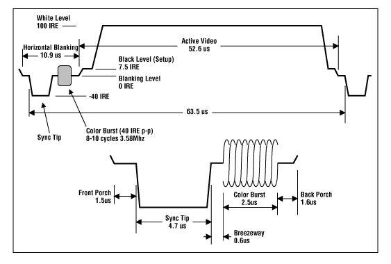 Quote:
I took some photos from the signals of my DVB decoder and my Amiga: DVB decoder: Amiga, using reduced CSYNC signal: Amiga using CVBS signal: As you can see, the most important difference is the lower level of the CSYNC signal. On the DVB decoder, It's a bit over 0v, but on the Amiga, It starts on 0v... And I think that the black level is a bit higher too. The CVBS signal from the amiga is quite similar to the CSYNC from the DVB decoder, but without the color burst. Note: I used the blue video signal as reference because the menu screen of the DVB decoder is almost blue, any other color signal looks similar. The amiga samples are from the workbench's disk screen (1.3). So, almost a white screen. Last edited by ferix; 15 September 2009 at 00:50. |
||||
|
|
|
15 September 2009, 01:10
|
#13 |
|
Registered User
Join Date: Jan 2008
Location: United Kingdom
Age: 46
Posts: 733
|
@Ferix,
So you are using an A500? The lack of colourburst on the video signal gave it away. The composite video output on the A500 is DC coupled from the video hybrid. On the A600/A1200 the composite video output is AC coupled from the CXA1145. The DC coupling will explain why the bottom of the sync from the A500 is not at 0V. Try a 470uF electrolytic capacitor on the video output. Connect the + terminal to the output from the Amiga and the - terminal to the wire going to the SCART lead. This replicates the output of the A600/A1200. Did you try using the output of the A520? I'll think about this some more and post again tomorrow. Thanks for the scope plots. Ian |
|
|
|
15 September 2009, 01:42
|
#14 | |||||
|
Registered User
Join Date: Sep 2009
Location: Spain
Age: 46
Posts: 95
|
Quote:
Quote:
Quote:
I think that the video levels are too high yet... Quote:
However, I looked at the CVBS signal from the A520, ant It looks like the one from the A500, but with the colour burst, of course. Quote:
P.D.: As you probably realized, English is not my first language, so I apologize if you get confused. |
|||||
|
|
|
15 September 2009, 01:50
|
#15 | |
|
Global Moderator
Join Date: Aug 2008
Location: Sidcup, England
Posts: 10,300
|
Quote:
There's no need to apologize for your English. It is very good from what I have seen. I congratulate you. There should be no risk of any confusion. Thanks to both you and Stedy for the very interesting thread. 
|
|
|
|
|
15 September 2009, 16:43
|
#16 |
|
Registered User
Join Date: Sep 2009
Location: Spain
Age: 46
Posts: 95
|
Well... It's starting to annoy me...
It seems that my TV LCD is too strict with the video signals... and I can't understand why... I made some measures, and that's what I got: From the TV decoder: Sync signal: Signal Offset (from 0v to sync): about 128mV Blanking level (top of sync): 415mV Video signal: Signal Offset: about 250mV Blanking level: 425mV From the Amiga: Sync signal: Signal Offset: 0V Blanking level: 668mV (top of sync). Video signal: Signal Offset: 410mV Blanking level: 410mV (there's no sync on video signal) For reference: Where A is the offset level, B is the blanking level, and C is the black level. It can't be so complicated... doesn't it? Last edited by ferix; 15 September 2009 at 18:16. |
|
|
|
18 September 2009, 00:45
|
#17 |
|
Registered User
Join Date: Jan 2008
Location: United Kingdom
Age: 46
Posts: 733
|
@Ferix,
I will dig out one of my A500's at the weekend and try a few experiments. I will feed the video through a summing amplifier so that I can apply DC offsets and see what happens. Will also try varying levels on the TTL Csync signal. As one of the TVs I tested was sensitive to the sync signal, it should provide a good test case. Have you tried the AC coupling of the composite video output? Also, on the CVBS output of the Amiga, add a potential divider using a 36 ohm and 39 ohm resistor. This will reduce the amplitude of the composite video to less than 1V. Some video decoders, like the ADV7180 or the SAA7118 can not cope with a video signal that is greater than 1V peak to peak. With colour composite video, the chrominance adds 200mV on top of the peak white. On the A500 composite there is no chrominance information of course. I really want to fix this, for my own satisfaction and to lay to rest the many issues experienced with RGB to SCART cables on modern TVs. On you TV, does it have the option to use RGB SCART or CVBS SCART? The Akura TV I tested had these modes + Y/C (S-Video) SCART options. The weekend is nearly here. Ian Last edited by Stedy; 18 September 2009 at 00:53. Reason: Added potential deivider trick |
|
|
|
18 September 2009, 01:07
|
#18 | |
|
Moderator
Join Date: Nov 2004
Location: Eksjö / Sweden
Posts: 5,602
|
Quote:
The reason is those TV sets were made to hook up to all kinds of equipment - VCRs, consoles, CCTV circuits, and also, SCART was THE interface and a "must have" for all consumers looking to buy a TV. Not so today. LCD, plasma etc are simply not made specifically to comply to a PAL video format. Any SCART is an add-on, not a requirement, and so, "displays that can display PAL via SCART RGB from any source the customer might own" is not a priority today. Same with composite. It's "be happy if it works" times. If the "most common specs" of the major manufacturers of RGB SCART-compliant displays were known, there would be a possibility to make an Amiga-dongle with a female scart plug, containing some simple electronics to clean the signal up and adapt it to comply to the narrower standard - maybe with some jumpers or switches to adapt to individual display brands, so "everyone can make their displays work / try the same methods you are trying now". And you could buy a simple scart-scart lead at the nearest consumer electronics store. I think this is an awesome idea, and I would buy a bunch of those in no time flat  Please make this and sell me some, or at least provide a schematic so I can make them This is a good thread, subscribing. If I can think a little about your test results I'll breadboard some solution together and try
|
|
|
|
|
19 September 2009, 14:24
|
#19 | |||||||||
|
Registered User
Join Date: Sep 2009
Location: Spain
Age: 46
Posts: 95
|
I'm sorry for the delay of my answer, but I'm having holidays, and I'm a bit far from my house. Actually, I'm at Tokyo... Very nice city, and very nice people too...
 Quote:
Quote:
Quote:
Quote:
Quote:
Quote:
Quote:
Quote:
Last edited by ferix; 19 September 2009 at 14:41. |
|||||||||
|
|
|
21 September 2009, 23:22
|
#20 |
|
Registered User
Join Date: Jan 2008
Location: United Kingdom
Age: 46
Posts: 733
|
Hello,
Just got back from the workshop. Over the weekend I replaced all the electrolytic capacitors in my A600 (will do the A1200 next weekend) and this has removed some of the spurious noise seen on the composite video output. It is still not perfect though. Whilst measuring the composite video output of my A600 on the scope, I noticed a problem, the scope had trouble locking to the composite video signal. As a sanity check I used a cheap CMOS colour camera, the scope locked fine and I could easily trigger on any particular line. With the A600 I could not. It looks like the equalising pulses from lines 1-3 are not quite correct, this appears to be causing my scope not to lock on. I need to borrow some equipment to verify my theory here, this will take a few days. There are numerous ways of creating a better video signal but I/we need to understand the problem first. In my day job, which involves developing video systems for aircraft we have numerous non-standard video types. With a few tweaks I have modern LCD panels synchronising to all sorts of video, it helps when you can programme the decoder input stage though. @Ferix, You're in Tokyo a busy place, hope you enjoy the break. For the MSX and the Sinclair Spectrum +2, were you also trying to use RGB mode? I don't suppose you fancy removing the back cover from the TV and taking some photos? @Photon, From experience you can get LCD TVs to sync to non-standard video, especially in composite mode easily. The domestic VCR outputs a Vsync signal that has +/-1us of jitter, for PAL/NTSC it should be +/- 37ns, yet the panel locks on. I built the PIC Tetris board, for test purposes  and this has equalising pulses missing and a large sync jitter, again LCD and CRT TVs locked onto it fine. and this has equalising pulses missing and a large sync jitter, again LCD and CRT TVs locked onto it fine.If I can work out what I need to do to make an adaptor PCB, it will be done. Will report back in a few days. Ian |
|
|
| Currently Active Users Viewing This Thread: 1 (0 members and 1 guests) | |
| Thread Tools | |
 Similar Threads
|
||||
| Thread | Thread Starter | Forum | Replies | Last Post |
| New cable for RGB - scart | Anders1984 | support.Hardware | 12 | 20 August 2013 23:40 |
| Photon's RGB Scart cable | Photon | support.Hardware | 5 | 21 October 2012 01:55 |
| Amiga RGB to Scart TV cable diagram | Anemos | Hardware mods | 11 | 16 July 2009 23:22 |
| RGB to scart cable | Hungry Horace | MarketPlace | 9 | 07 November 2007 10:06 |
| rgb->scart cable | jrom | support.Hardware | 26 | 23 December 2004 23:04 |
|
|


