
|
 07 June 2008, 16:34
|
#21 | |
|
Ya' like it Retr0?
Join Date: Jul 2005
Location: United Kingdom
Age: 49
Posts: 9,768
|
Quote:
Games, would not 
|
|

|
|
07 June 2008, 17:24
|
#22 |
|
Posts: n/a
|
@Zetro, yeah I've noticed. Just been messing about with them. WB looks really nice in Multiscan 640*400. But obviously when I go to use an Intuition program such as Octamed 4 then all hell breaks loose.
Besides, even with a 68030@50, using 256 colours in 640@400 is useless. And I suppose even with external devices such as EZVGA from eyetech are going to be a load of rubbish too, because all the weight of running in these modes is still upon the processor. So although it looks nice, its completely redundant, because its like carrying a dead horse. |
|
07 June 2008, 18:13
|
#23 |
|
Ya' like it Retr0?
Join Date: Jul 2005
Location: United Kingdom
Age: 49
Posts: 9,768
|
An RTG Amiga, is a wonderfull Experience!
if you ever get the opportunity, one should not miss out on it! |
|
|
|
07 June 2008, 21:05
|
#24 |
|
Posts: n/a
|
Yeah Zee, that seems like the most sensible option really. But for an a1200 its just too much expansion and expense!
|
|
08 June 2008, 00:30
|
#25 |
|
Ya' like it Retr0?
Join Date: Jul 2005
Location: United Kingdom
Age: 49
Posts: 9,768
|
I have to agree.... but i have some theories that i hope to try out this year at the UNI lab
 my hope is to be able to create a zorro2 to isa2 port that will run a 2/4mb video card .... hopefully.... this way, one could be put internally in an A1200 / CD32 / mayhap if i can get it working for a zorro port it could happen for A1000 / A500 / even a600 after modification. |
|
|
|
08 June 2008, 07:58
|
#26 |
|
Posts: n/a
|
Do you have to do the a520 adaptor hack in order to get an S-Video Composite connecter?
I assume if you'd taken the AV transcoder VGA route you'd still only be limited to the Amiga native 50Hz x 15.60Khz frequently anyway - right? So Multiscan/Productivity Modes will not work. The point I'm trying to make is, although the device will up-scale/de-interlace to a solid high definition resolution the actual physical resolution of the Amiga display hasn't changed. So you'll only end up benefiting from, for arguments sake, say SuperHires 1280*512 Interlaced. How are screenmode unique parameters handled too. IE: Unclick default option and resize to... 1. SuperHires 640(1280)*512 (still very low work area) 2. Overscan a large physical area 1280*1024, would this be rescaled to fit the screen in VGA mode??? |
|
08 June 2008, 14:48
|
#27 |
|
Ya' like it Retr0?
Join Date: Jul 2005
Location: United Kingdom
Age: 49
Posts: 9,768
|
@Skippstah
Hmmmmm well the 1280x512, is bigger than it sounds, or it could just be my 42" Plasma TV lol, the Screen is upscaled to 1280x1024 and is then input into VGA input on the TV. infact perhaps a little toooo big me thinks. I find 640x512 quite comfy  Alas I haven't tried any Overscan modes, although i would go out on a limb and state that these wont be re-scaled, but i will try later tonight and let you know. |
|
|
|
08 June 2008, 14:54
|
#28 | |
|
Thalion Webshrine
Join Date: Jan 2004
Location: Oxford
Posts: 14,335
|
Quote:
|
|

|
|
09 June 2008, 17:57
|
#29 | |
|
Registered User
Join Date: Feb 2005
Location: montreal / canada
Age: 47
Posts: 722
|
Quote:
|
|
|
|
|
20 July 2014, 17:41
|
#30 | |
|
Unregistered User
Join Date: Sep 2012
Location: Copenhagen / DK
Age: 43
Posts: 4,190
|
Quote:
I would like to make an RGB->VGA cable for the monitors which support 15kHz Hsync, like the C= adapters: 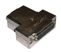 Looking at the schematic, I can see some possible errors, like the VSYNC and HSYNC labels switched around and also that the HSYNC line is connected to Amiga pin 22 where it should be pin 11. Also, pins 9, 10, 12 & 13 of the IC should be connected to Gnd. Otherwise I think it should be possible to build this by cutting a VGA cable and putting the buffer circuit inside the SUBD shell. |
|
|
|
|
30 September 2015, 20:07
|
#31 | |
|
Registered User
Join Date: Apr 2015
Location: Lisbon
Posts: 65
|
Quote:
Hi Demo, I know this is a old post, but why you should connect PIN's 9, 10, 12 and 13 of IC to GND? regards, 1NOM155 |
|
|
|
|
30 September 2015, 21:35
|
#32 | |
|
Unregistered User
Join Date: Sep 2012
Location: Copenhagen / DK
Age: 43
Posts: 4,190
|
Quote:
I built the circuit, only I used a 7404 instead as that was what I had. It works great with my 2001FP monitor. |
|
|
|
|
08 October 2015, 16:56
|
#33 | |
|
Registered User
Join Date: Apr 2015
Location: Lisbon
Posts: 65
|
Quote:
|
|
|
|
|
08 December 2015, 17:22
|
#34 |
|
Registered User
Join Date: Dec 2015
Location: Oslo / Norway and Tokyo / Japan.
Posts: 23
|
Sorry for my possible ignorance, but how will the IC on the previous page negate the signal?
I suppose that is the purpose of using the IC, to negate the sync signals? For me, using just connections to each RGB, each ground, and the sync signals is enough. I guess some monitors cannot handle that, so you want to use the IC? The reason why I ask, 1 and 1 on the inputs of an AND gate gives 1, 0 and 0 gives 0... so what is then the merit? Is there something I am missing here?! Thanks! |
|
|
|
08 December 2015, 17:49
|
#35 | |
|
Unregistered User
Join Date: Sep 2012
Location: Copenhagen / DK
Age: 43
Posts: 4,190
|
Quote:
|
|
|
|
|
08 December 2015, 18:03
|
#36 | |
|
Registered User
Join Date: Dec 2015
Location: Oslo / Norway and Tokyo / Japan.
Posts: 23
|
Quote:
What voltage value would you recommend for the capacitor? Can it be ceramic? Also, would it be an advantage to connect the grounds individually to the proper grounds at the other end? Last edited by olav; 08 December 2015 at 18:18. |
|
|
|
|
06 March 2018, 10:48
|
#37 | |
|
-
Join Date: Jul 2003
Location: Helsinki / Finland
Age: 43
Posts: 9,861
|
Quote:
The text descriptions for the pins are correct in the picture, but in the schematic, the HSYNC and VSYNC wire labels are swapped, but more importantly, the wire marked as VSYNC is not connected to a sync pin, instead it is connected to the +12V supply! This will cause damage. Seems no-one built it anyway back in 2008, as the smoke wouldn't have gone unnoticed if someone had. I can't edit the post to notify anyone, so this will have to do. |
|
|
|
|
06 March 2018, 12:08
|
#38 |
|
Registered User
Join Date: Nov 2014
Location: NSW/Australia
Posts: 462
|
I have a schematic and pcb gerbers for a replica of the commodore adaptor (DB23->HD15) using an smd 74hct08. Will get it up in a public place in a week or so. Need to work on a second version that fits nicely in a backshell.
|
|
|
|
06 March 2018, 13:30
|
#39 |
|
Amigan - an' lovin' it!!
Join Date: Nov 2010
Location: Nottingham, UK
Age: 55
Posts: 557
|
@Jope - Good spot. I didn't see this thread previously, but read it with interest now it's been bumped. A decent solution to my straighforward, yet flickery, RGB-SCART connection would be nice.
|
|
|
| Currently Active Users Viewing This Thread: 1 (0 members and 1 guests) | |
| Thread Tools | |
 Similar Threads
|
||||
| Thread | Thread Starter | Forum | Replies | Last Post |
| JS Technology RGB/VGA | Parsec | Retrogaming General Discussion | 3 | 20 December 2010 16:02 |
| Passive RGB to VGA? | whitebird | support.Hardware | 8 | 28 September 2010 10:27 |
| Simple RGB to VGA | mihcael | support.Hardware | 15 | 12 February 2009 21:17 |
| RGB to VGA | tonyyeb | support.Hardware | 8 | 17 October 2008 09:25 |
| VGA adapter to connect a VGA/Multiscan monitor to the Amiga RGB port | Tuffy | support.Hardware | 4 | 07 April 2008 09:29 |
|
|


