
|
 05 January 2011, 17:09
|
#1 |
|
Registered User
Join Date: Dec 2009
Location: Toronto, Canada
Posts: 63
|
Built my own: Amiga RGB to S-Video + composite adaptor small issue though...
Hi there, I built this project (picutres to come) on a vero PC board with a 15 pico farad capacitor, and the NTSC colourburst crystal (3.795 etc Mhz)
I am not getting any colour from either the Composite out, or the Svideo jack. I'm guessing, from what I have read on the "Amiga RGB to S-Video + composite adaptor" thread that the capacitor might be the issue. If the issue was just the svideo jack then the problem might be the chroma out put, ( bad connection etc ) but seeing as it's on both the composite (generated in chip) and the svideo, I'm guessing it's a timing issue with the crystal and capacitor. I will try a 20 pf. If I need a variable one. what would be the best value to purchase?... Last edited by waltermixxx; 05 January 2011 at 17:10. Reason: change title a bit |

|
|
05 January 2011, 18:28
|
#2 |
|
Ya' like it Retr0?
Join Date: Jul 2005
Location: United Kingdom
Age: 49
Posts: 9,768
|
@walter
I think you need less than 15pf, firstly try it without a capcitor, and then *maybe a 10pf unit. |
|
|
|
06 January 2011, 00:20
|
#3 |
|
Registered User
Join Date: Dec 2009
Location: Toronto, Canada
Posts: 63
|
he he, I was going to...
 one of the posts mentioned no cap at all one of the posts mentioned no cap at all i was going to start with that... i have a bunch of small ones to try as well,but a variable would allow me to fine tune incase it changes with another monitor... but I suspect a a 0 to 20 pf would be good thanks for your reply, I will post pics once I get it sorted out... Cheers
|
|
|
|
06 January 2011, 01:19
|
#4 |
|
Ruler of the Universe
Join Date: Mar 2010
Location: Lanzarote/Spain
Posts: 6,190
 |
Didn't you find more smilies ?
|
|
|
|
06 January 2011, 02:12
|
#5 |
|
Registered User
Join Date: Dec 2009
Location: Toronto, Canada
Posts: 63
|
It's a sickness,
you should see my emails at work, not sure when it started, but but I usually have to go through my emails before I send them to remove extraneous smiley faces... luckily it only manafests itself in the written medium... otherwise folks might think I'm meniacle. Cheers
|
|
|
|
06 January 2011, 02:27
|
#6 |
|
Registered User
Join Date: Dec 2009
Location: Toronto, Canada
Posts: 63
|
Picture of the one I built
This is the one I built on a vero board.
it did not take very long to do, and I used a SOIC to 16pin dip adapter to make the process a bit easier... Digi-key has both the chip (for around $11.00 canadian) and the soic adapter... ($6.00) so together a little hefty, but fun to build... I will remove the 15 pf cap and see what happens
|
|
|
|
06 January 2011, 06:12
|
#7 |
|
Registered User
Join Date: Dec 2009
Location: Toronto, Canada
Posts: 63
|
Well now I am depressed... I could not find a cap that would allow it to sync up to this little LCD monitor... the picture remained in black and white, but I had issues with that monitor before... so I hooked it up to my 32" LCD HD tv, via svideo, and the blue signal came through fine, but the red and green looked odd. I tried various caps with that tv and either got black and white or a picture with messed up colours... I did verify my red blue green where going the appropriate pin n the chip, hsync and vsync appeared to be fine as I was getting a picture...
by the way I was testing this with my Atari 1040STE, I will have to fire up the Amiga 500 and see what kind of luck I get with that... |
|
|
|
06 January 2011, 07:51
|
#8 |
|
Ya' like it Retr0?
Join Date: Jul 2005
Location: United Kingdom
Age: 49
Posts: 9,768
|
@walter
I noticed you have adapted the design with the addition of an LED, now the Amiga +5 on the Video out is 100mA (at maximum), the AD724JR requires a minimum of 42mA - its quite likely you are not providing enough power to run both devices. |
|
|
|
06 January 2011, 11:46
|
#9 |
|
Registered User
Join Date: Jun 2010
Location: PL?
Posts: 2,775
|
LED can be low power type - draw like 3 - 5mA - not a problem, IMO best is use +12V and some voltage regulator IC (it gives cleaner supply)
|
|
|
|
07 January 2011, 01:36
|
#10 |
|
Registered User
Join Date: Jan 2008
Location: United Kingdom
Age: 46
Posts: 733
|
Waltermixx,
Disconnect your 3.57 MHz crystal and use the NTSC carrier clock from pin 15 of the RGB port. This will be time aligned with the sync pulse edges, important for good colour definition (if possible with NTSC). Have you ensured that pin 1 of the AD724 is pulled high to select NTSC encoding? Is pin 12 pulled low to select FSC (3.57 MHz) clock input? Normally a black and white picture is a result of an incorrect carrier frequency. Ian |
|
|
|
07 January 2011, 03:50
|
#11 | |
|
Registered User
Join Date: Sep 2009
Location: San Antonio, TX USA
Age: 50
Posts: 1,185
|
Quote:
The black and white problem, looks like is related to color carrier between PAL and NTSC as stated above by others. |
|
|
|
|
07 January 2011, 04:51
|
#12 |
|
Ya' like it Retr0?
Join Date: Jul 2005
Location: United Kingdom
Age: 49
Posts: 9,768
|
@Walter
Sorry, I have to admit I am a little confused - you say you have been using this on the Atari 1040STE? Video Pin-Out 1 - NC - *Audio Out 2 - Composite Video 3 - NC - GPO 4 - M detect (if low *grounded* ST enters Hires Monocrome video mode) 5 - NC - *Audio In 6 - Green 7 - Red 8 - +12V (520ST has GND here) 9 - Hsync - Horiz sync 10 - Blue 11 - NC - Monocrome Video 12 - Vsync - Vertical Sync 13 - Ground Where are you sourcing your +5v ? Are you sure you are outputting 60Hz refresh and not 50Hz Vertical refresh? heres an alternative to an external SVideo output - should the 1040STe have a modulator then you can source the Chroma and Luma from there here is how to do it also might be relevant is this link Alexh put up a while back; an Atari ST SVideo Adapter - it still needs a little work but have a look it might help. I will say that it does sound that either 1. the video signal is IN mono mode 2. the colour clock is no functioning properly (oscillator and or Ad724 setting) Good luck with your investigations, let us know how you get on =) |
|
|
|
10 January 2011, 04:54
|
#13 |
|
Registered User
Join Date: Dec 2009
Location: Toronto, Canada
Posts: 63
|
hi there, wow I appreciative of all the replies... thank you.
I am using it with an atari STE, mono detect line is floating so ST produces colour out. I do have an amiga 500 I will try with as well, just to make sure it's not the circuit, as someone suggested that would be a good idea. I will post my findings... the Amiga does make it easy by providing a clock for the circuit... ( If it works with the amiga, I will remove the crystal and use it with my amiga, and perhaps doe the svideo mod on the ste. I do have an atari colour rgb monitor, I was just hoping to use an LCD monitor as it's lighter and uses less electricity... I was thinking of doing the Svideo mod to my 1040ste as it does have a modulator, or simply using the composite video out on pin two of the 13 pin din, but the crisp image provided by svideo a million times better I'm just afraid of killing my STE doing the mod... the 5 volts is coming from a power adapter, a switching variety for use with a USB hub, it's rated at 1 amp so plenty of power there for the LED i checked the voltage with a meter while powering the circuit and it's still 5 volts. I may get 5 volts from the 15 pin ste joystick port... that may help too... I will post how it goes with the Amiga 500. Thanks again...  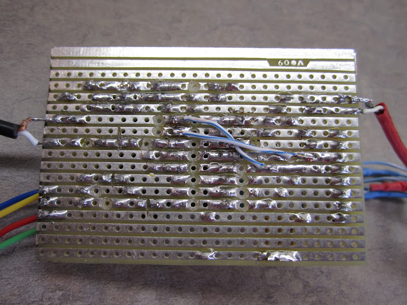 The two pin socket is where i tried various caps, 10, 12, 15, 18, 22, 30 pf. I'm sure there is a magic number in there somewhere
Last edited by TCD; 10 January 2011 at 08:04. Reason: Back to back posts merged. Use the edit function. |
|
|
|
11 January 2011, 01:36
|
#14 |
|
I hate potatos and shirts
Join Date: Oct 2007
Location: Sao Leopoldo / Brazil
Age: 58
Posts: 3,482
  |
Where you found this lovely SMD-to-DIP adaptor? Me likes it!
|
|
|
|
11 January 2011, 07:09
|
#15 | ||
|
-
Join Date: Jul 2003
Location: Helsinki / Finland
Age: 43
Posts: 9,864
|
Quote:
Quote:
|
||
|
|
|
18 January 2011, 03:29
|
#16 |
|
Registered User
Join Date: Dec 2009
Location: Toronto, Canada
Posts: 63
|
I have not had a chance to try this with my Amiga 500 yet but will post when I get to.
|
|
|
|
19 January 2011, 12:20
|
#17 |
|
Registered User
Join Date: Dec 2009
Location: West Australia
Age: 47
Posts: 210
|
Could you please post some screen shots?
|
|
|
|
24 January 2011, 22:36
|
#18 | |
|
Registered User
Join Date: Oct 2009
Location: Salem, OR
Posts: 1,770
|
The ST is known to (sometimes??) have problems with the AD724.
There's a thread on it on atariage in their ST section... desiv Found it: Quote:
http://www.atariage.com/forums/topic...ge__hl__svideo Last edited by desiv; 24 January 2011 at 22:43. |
|
|
|
|
26 January 2011, 22:57
|
#19 | |
|
Registered User
Join Date: Jun 2010
Location: PL?
Posts: 2,775
|
Quote:
It works but i prefer background paper (waxed paper) from laser printable labels/stickers |
|
|
|
|
18 December 2012, 21:35
|
#20 |
|
Posts: n/a
|
Sorry for grave digging but I have just built this circuit and I searched all over the internet for an answer to this and eventually figured it out so I thought I'd give an answer.
I don't know what capacitor you have in your circuit but in the datasheet it will give you a 'shunt capcitance' to be used with it, typically 18 or 22pF. Now, the crystal needs this much capacitance in parallel, but you need a capacitor value such that the cap value + any latent capacitance in your circuit = the shunt capacitance. On PCBs the latent capacitance is quite small, but with strip/vero board the linear tracks cause _much higher_ latent capacitance in your circuit, much too high for the crystal, so in fact you probably already have far too much there. I spent days playing with this and was going a bit crazy. I then realised this, and cut all the traces in my strip board connected to pin 3/the capcitor to make them as short as possible (no left over strip that goes nowhere). Before everything was black and white and blurry whatever I did, now its in perfect colour! Also, you can use a little trim capacitor to tune it to the right value, or just try some different values. Now I cut the traces I even get colour with no capacitor present. Probably you've forgotten this project a long time ago, but maybe this can help someone out! Last edited by Munchausen; 18 December 2012 at 21:41. |
| Currently Active Users Viewing This Thread: 1 (0 members and 1 guests) | |
| Thread Tools | |
 Similar Threads
|
||||
| Thread | Thread Starter | Forum | Replies | Last Post |
| Amiga RGB to S-Video + composite adaptor | narmi | Hardware pics | 431 | 11 September 2017 19:23 |
| Amiga A1200 RGB & composite video problem solution! | Anemos | support.Hardware | 24 | 24 September 2015 08:36 |
| A1200 composite/rgb video port flakey? | Amiga1992 | support.Hardware | 2 | 17 April 2012 23:44 |
| RGB to S-Video / Composite Adaptor | Charlie | Hardware mods | 3 | 30 January 2011 14:13 |
| For sale a NEW RGB CGA to S-Video and Composite Video converter | Vars191 | MarketPlace | 0 | 11 January 2009 05:09 |
|
|


