
|
 30 September 2019, 22:36
|
#501 |
|
Registered User
Join Date: Sep 2019
Location: Amsterdam / The Netherlands
Posts: 48
|
I recently bought a version of this card from AMIGAstore.eu and got it installed in the 0.5MB chip + 1.5MB slow configuration. (Thanks Jope for helping debug my JP2/JP7A brainfart!) Unfortunately neither the OS or the Amiga Test Kit find the RTC on board. SetClock RESET doesn't do the trick. I've measured that the Epson RTC-72421A chip does get 3V from the battery (pins 9 and 18) but other than that I'm not sure where to look at. Any ideas what might cause the RTC not to be found?
I did have the card installed for a moment with an incorrect JP2/JP7A setup. May this have killed the RTC on the card? During the installation process the TOD part of my CIAA also died. Not sure if it's related or not. |

|
|
01 October 2019, 19:56
|
#502 |
|
Registered User
Join Date: Jul 2017
Location: Germany
Posts: 205
|
If resetting the clock does not help, then something may be damaged. Can you see the RTC with keirf systest?
|
|
|
|
02 October 2019, 06:30
|
#503 | |
|
Registered User
Join Date: Dec 2018
Location: UK
Posts: 1,715
|
Quote:
If A500+ there is also a JP9 jumper that tells the system to look for the internal RTC (default) or the external RTC. |
|
|
|
|
02 October 2019, 16:30
|
#504 | ||
|
Registered User
Join Date: Sep 2019
Location: Amsterdam / The Netherlands
Posts: 48
|
Quote:
Quote:
I used to have a Microbotics M501 512k card with an RTC installed and that one did work but that was prior to the JP2/JP7A changes. I haven't tested it again afterwards - would that require undoing the JP2 modification? I swapped the CIAs and that moved the TOD problem to CIAB, making clock work again in the OS. However, that didn't affect the RTC not being found. |
||
|
|
|
02 October 2019, 17:27
|
#505 |
|
Registered User
Join Date: Dec 2018
Location: UK
Posts: 1,715
|
The clock read (_CLKRD) and write (_CLKWR) signals goes to Gary - pins 22 and 23.
Try cleaning the pins and socket of Gary. |
|
|
|
02 October 2019, 22:37
|
#506 |
|
Registered User
Join Date: Dec 2018
Location: UK
Posts: 1,715
|
And, if you can get it to your A500, try the RestartClock tool:
http://thomas-rapp.homepage.t-online...startClock.lha I suggest the easiest method, is to us a Gotek drive with a Workbench ADF, and another ADF created with Directory Opus and put RestartClock on it. You can then boot up the Workbench ADF, start a CLI/shell, swap to the other ADF, and run the RestartClock command. |
|
|
|
03 October 2019, 10:53
|
#507 | |
|
Registered User
Join Date: Sep 2019
Location: Amsterdam / The Netherlands
Posts: 48
|
Quote:
Thanks! Tried it but it didn't do anything. I could write my own code to access the RTC through DC0000-DCFFFF but I doubt this would be that beneficial if the SysTest (for example) won't find the clock at all. |
|
|
|
|
03 October 2019, 11:41
|
#508 |
|
Registered User
Join Date: Dec 2018
Location: UK
Posts: 1,715
|
So maybe you could check the chip select trace (_XCLKCS) to make sure it is OK and asserted (_XCLKCS is active low).
|
|
|
|
03 October 2019, 12:22
|
#509 |
|
Registered User
Join Date: Dec 2018
Location: UK
Posts: 1,715
|
And looking at the schematics/gerbers - there seems to be a jumper to enable the clock? Is this jumper enabled on your board?
|
|
|
|
03 October 2019, 23:02
|
#510 | |||
|
Registered User
Join Date: Sep 2019
Location: Amsterdam / The Netherlands
Posts: 48
|
Quote:
Quote:
Quote:
 One thing potentially worth mentioning: the system does have a TerribleFire TF530 installed. However, an another RTC did work with it without issues. |
|||
|
|
|
04 October 2019, 07:58
|
#511 |
|
Registered User
Join Date: Dec 2018
Location: UK
Posts: 1,715
|
Have you tried without the TF? And do you still have the other RTC to try out. At least you can rule out your A500 motherboard.
When I had similar RTC issues on my A500+ - it was not found or the clock was not ticking - I tried reflowing the pins of the sockets and components. But this was on a battery damaged A500+ Eventually I replaced the RTC chip itself and it was working and stable since then. It is a shame the RTC chip on your memory board is not socketed, but you can still replace it if you have the tools and skillset. However, since it is new you might want to consider returning it and getting a replacement, but you should try to rule out your A500 motherboard first. |
|
|
|
04 October 2019, 11:51
|
#512 | |||
|
Registered User
Join Date: Sep 2019
Location: Amsterdam / The Netherlands
Posts: 48
|
Quote:
 Quote:
|
|||
|
|
|
08 October 2019, 14:41
|
#513 |
|
Registered User
Join Date: Dec 2018
Location: UK
Posts: 1,715
|
With the board in the Amiga and powered on, what is the voltage at the RTC chip? It needs be within usually 2V to 6V. If it is out of range - i.e. if it is higher than 6V the RTC chip with not work.
I just found this out with one of my memory expansion cards. With the battery removed and card plugged in and powered by the Amiga, the RTC chip was getting 8.1V, due to the 12V source. |
|
|
|
15 November 2019, 20:09
|
#514 |
|
Registered User
Join Date: Sep 2019
Location: Göteborg / Sweden
Posts: 32
|
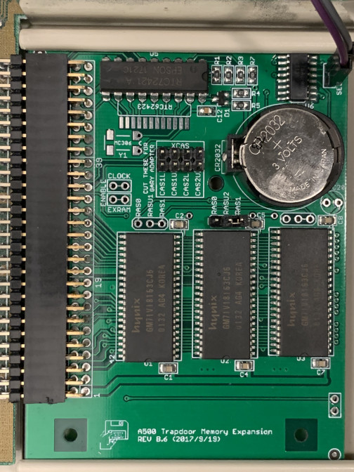
I had the exact same problem with my RTC not working on the same expansion board, it turned out to be a faulty IC.
By chance I happened to have a RTC in an old memory card that was in a socket. I took that IC and piggy backed it on the suspected faulty RTC on my expansion board, and to my surprise it worked! So if you have not solved your issue yet, and happen to have a RTC in a socket, try to piggy back it ;-) *edit* be sure that you have a tight fit when placing the other RTC over the RTC on the expanison, see picture *edit* Last edited by CrowStudio; 15 November 2019 at 20:15. Reason: adding picture |
|
|
|
25 November 2019, 19:34
|
#515 |
|
Zone Friend
Join Date: Mar 2004
Location: Middle Earth
Age: 40
Posts: 2,127
|
Hi guys. So the most max RAM you can have on a A500 with out using a gary adapter is just 512k RAM? and on an A500+ that 512k ram goes straight to $80000-$fffff instead of $c00000 like on the A500?
Thanks |
|
|
|
25 November 2019, 20:55
|
#516 | |
|
Unregistered User
Join Date: Sep 2012
Location: Copenhagen / DK
Age: 43
Posts: 4,190
|
Quote:
|
|
|
|
|
26 November 2019, 08:23
|
#517 | ||
|
-
Join Date: Jul 2003
Location: Helsinki / Finland
Age: 43
Posts: 9,861
|
Quote:
Quote:
|
||
|
|
|
26 November 2019, 08:43
|
#518 |
|
Zone Friend
Join Date: Mar 2004
Location: Middle Earth
Age: 40
Posts: 2,127
|
Thanks, Yes I was meaning just in the trap door. Most searches just showed a 512k Ram expansion, memory maps, or expansions with the gary adaptors.
Mainly wondering because those other expansions looked like they would have voided the warranty back in the 80s early 90s. I see a post on this board by zetro regarding bank switching. |
|
|
|
26 November 2019, 08:49
|
#519 |
|
Mighty Pirate
Join Date: Dec 2017
Location: On the borderline
Age: 44
Posts: 177
|
Just a note: on an A500+, you can have 1 MB extra chip RAM in the trapdoor, and this board also works for that.
|
|
|
|
05 May 2020, 13:52
|
#520 |
|
Registered User
Join Date: May 2020
Location: Berlin, Germany
Posts: 2
|
katarakt made me aware that the Rev C6 (SOJ40) is still documented here as *UNTESTED*
http://eab.abime.net/showpost.php?p=1131907&postcount=2 The Rev C6 works great as a 512k Slowram Extension on the A500 Rev.5 and Rev.6 And I use successfully the Rev C6 as a 1M Chipram Extension on the A500 Rev.8 I found the SOJ40 memory chips on an old AGP graphics card Last edited by MalleB; 05 May 2020 at 13:58. |
|
|
| Currently Active Users Viewing This Thread: 1 (0 members and 1 guests) | |
| Thread Tools | |
 Similar Threads
|
||||
| Thread | Thread Starter | Forum | Replies | Last Post |
| Modern Trapdoor RAM killed my A500 | Silwuff | New to Emulation or Amiga scene | 20 | 10 January 2021 15:36 |
| Homemade A500 trapdoor expansion? | cabal | Hardware mods | 5 | 01 December 2014 21:44 |
| WTB: two(2) A500 trapdoor slot covers | papa_november | MarketPlace | 0 | 25 December 2008 09:17 |
| Trapdoor expansion options for A500 | Impakt | support.Hardware | 7 | 20 March 2008 06:05 |
| A500 Plus Trapdoor Expansion | TheCorfiot | support.Hardware | 10 | 14 March 2008 16:42 |
|
|


