
|
 17 February 2018, 16:29
|
#1 |
|
Registered Whdload user
Join Date: Oct 2006
Location: Finland
Age: 48
Posts: 532
|
Sync on green with Sony BVM-20F1E?
I have some retro computers and I want to hook them up into my precious Sony
 The main idea is that I *don't* have to detach/attach any wires ever, when I want to use the computers. I have two sets of rgb inputs available (all BNCs), 1: RGB+Hsync+Vsync and 2: RGB + sync on green. For number of reasons it would be really convenient to hook the A600 to the 2nd rgb input with the sync on green (with no discrete sync inputs). I know my A600 does not provide the sync on green, but what about this: I hook the R and B to the appropriate inputs and then *combine* G and direct signal from the A600 composite out to the G+Sync input on the monitor The main idea is that I *don't* have to detach/attach any wires ever, when I want to use the computers. I have two sets of rgb inputs available (all BNCs), 1: RGB+Hsync+Vsync and 2: RGB + sync on green. For number of reasons it would be really convenient to hook the A600 to the 2nd rgb input with the sync on green (with no discrete sync inputs). I know my A600 does not provide the sync on green, but what about this: I hook the R and B to the appropriate inputs and then *combine* G and direct signal from the A600 composite out to the G+Sync input on the monitor  Should/would this work? Should/would this work?I know I can buy more addon input cards for the Sony, but they're just very expensive :/ |

|
|
17 February 2018, 16:35
|
#2 |
|
Registered User
Join Date: Jun 2016
Location: Stoke-On-Trent, England
Posts: 450
|
If you want multiple inputs why not get a cable such as https://www.retrogamingcables.co.uk/...y-pvm-monitors which takes care of the sync and then get a decent quality SCART switch?
Such as http://www.ebay.co.uk/itm/Premium-Ba...EAAOSwopRYbSX6 Thats the setup I use on my NEC XM29+ |
|
|
|
17 February 2018, 16:43
|
#3 | |
|
Registered Whdload user
Join Date: Oct 2006
Location: Finland
Age: 48
Posts: 532
|
Quote:
My plan is to use the other solely for the Amiga and the other via the LM1881 for the rest of the computers.
|
|
|
|
|
17 February 2018, 17:07
|
#4 |
|
Registered User
Join Date: Jun 2010
Location: PL?
Posts: 2,741
|
You need to combine CSYNC (pin 10 on DB23 video connector) with G signal. LM1881 is used to separate sync pulses so it will act in opposite way (unless you doing some video switching matrix to deal with various type of video signals and at the output of this switching matrix you wish to produce unified RGB + H and V sync)
|
|
|
|
17 February 2018, 17:45
|
#5 | |
|
Registered Whdload user
Join Date: Oct 2006
Location: Finland
Age: 48
Posts: 532
|
Quote:
https://drive.google.com/open?id=164...FcRyao07ydtc5L |
|
|
|
|
18 February 2018, 00:59
|
#6 | |
|
Registered User
Join Date: Jun 2010
Location: PL?
Posts: 2,741
|
Quote:
|
|
|
|
|
18 February 2018, 10:17
|
#7 | |
|
Registered Whdload user
Join Date: Oct 2006
Location: Finland
Age: 48
Posts: 532
|
Quote:
Code:
Analog component (Y/R–Y/B–Y, RGB) signals Signal level Y/R–Y/B–Y Y: 1 Vp-p ±6 dB R–Y: 0.7 Vp-p ±6 dB B–Y: 0.7 Vp-p ±6 dB R/G/B 1 Vp-p ±6 dB (sync on G) Frequency characteristics Y 100 Hz to 10 MHz ±1dB R–Y/B–Y 100 Hz to 6 MHz ±1dB R/G/B 100 Hz to 10 MHz ±1dB Chrominance signal/luminance signal Delay time error 30 nsec max. Gain error 5% max. Aperture compensation (Y/R–Y/B–Y) 6 dB min. (5 MHz) Return loss –46 dB min. (7 MHz) 
|
|
|
|
|
19 February 2018, 09:25
|
#8 |
|
Registered Whdload user
Join Date: Oct 2006
Location: Finland
Age: 48
Posts: 532
|
Regarding the origonal topic: As I currently have hooked up the A600 to the default RGB inputs combining the TTL level H and V syncs (working fine), can someone tell me, if the same concept would work via the add-on card also according to the specs? Here are the specs for the original RGB compared to the specs of the add-on card (direct quotes from the corresponding manuals):
Original (works): "Composite sync: 0.3 to 8 Vp-p, negative, high impedance" Add-on card (haven't tested yet): "Y/R–Y/B–Y Y: 1 Vp-p ±6 dB R–Y: 0.7 Vp-p ±6 dB B–Y: 0.7 Vp-p ±6 dB R/G/B 1 Vp-p ±6 dB (sync on G)" 
|
|
|
|
20 February 2018, 18:54
|
#9 |
|
Registered User
Join Date: Jun 2010
Location: PL?
Posts: 2,741
|
Composite sync on Amiga is available separately and it may be connected directly to dedicated composite sync input however in case of SyncOnGreen it should have IMHO 300mV level so i would strongly advise to use 600Ohm resistor used as voltage divider. Amiga should deliver 1V RGB signal so you should be on safe side (seem from your perspective monitor is capable to accept video level between 0.5 and 2V).
Be sure that proper termination (75Ohm) is activated (some monitors may have embedded terminators but some require external ones so you need to use T connector) |
|
|
|
20 February 2018, 20:06
|
#10 | |
|
Registered Whdload user
Join Date: Oct 2006
Location: Finland
Age: 48
Posts: 532
|
Quote:
Sorry to bother you constantly
|
|
|
|
|
21 February 2018, 11:30
|
#11 | |
|
Registered User
Join Date: Jun 2010
Location: PL?
Posts: 2,741
|
Quote:
RGB this is 3 signal - 3 different cables required, if you have separate H and V sync then additionally you need 2 more wires, combining H and V to composite sync you can use only one wire and if you combine Green with C Sync they you need in total 3 wires so you have same number wires as for RGB i.e. minimal required. So if your goal is to have SoG (Sync on Green) then you need in total 3 BNC 75Ohm terminators, 4 BNC T connectors, 3 T connectors must be on BNC monitor inputs like this 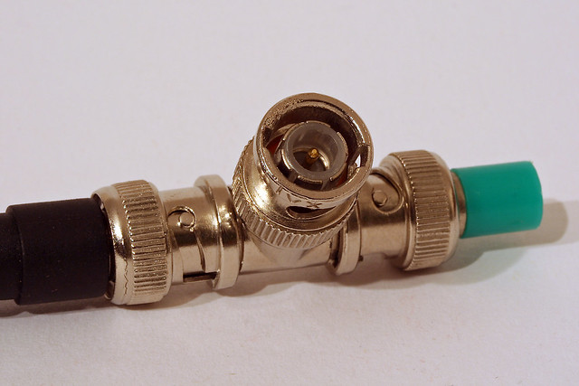 Green input must be feed by 2 wires - Green and Composite Sync where CS should be connected trough 300 - 600Ohm resistor . You can combine Green and level limited (resistor) CS by connecting Green and level limited CS trough another T-connector. 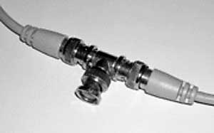 Be sure that you using BNC 75 Ohms (they are also 93ohm very rare and commonly available 50 Ohm BNC equipment - 50 Ohm is used for measurement and RF equipment - main difference between those BNC are inner pin thickness - combining different impedance BNC you may have lousy connectivity and/or risk mechanical damage of inner BNC socket). Buy BNC equipment or properly marked or from reputable source (a bit of contradictory but i personally experienced reputable brand from good source incorrectly marked so nowadays i must say: people just don't care so you must care twice more). |
|
|
|
|
21 February 2018, 20:34
|
#12 | |
|
Registered Whdload user
Join Date: Oct 2006
Location: Finland
Age: 48
Posts: 532
|
Quote:
I made an "voltage divider" adapter, which should lower the voltage of the sync to 0.3v (sync on green seems to be 0.7v (green) + 0.3v (sync). I *tried* to follow some instructions regarding the basics of regulators and voltages. Please don't laugh  I really know nothing about electronics... Here's how it looks like. If I measure the resistance, it shows me ~2.8kOhm. I really know nothing about electronics... Here's how it looks like. If I measure the resistance, it shows me ~2.8kOhm. 
|
|
|
|
|
22 February 2018, 18:46
|
#13 | |
|
Registered User
Join Date: Jun 2010
Location: PL?
Posts: 2,741
|
Quote:
No laugh on my side - first you trying to do working solution and it looks OK (many prototypes looks very similar) - second this is part of bigger discussion from other forum about people attitude and/or lack of it (somehow i see you are not from US but from Finland so this may be explanation) anyway good work  Now lets go to main topic. Do not forget that important part of your divider is 75 Ohm termination - that's why you need only one resistor - second is on monitor input or on external 75 Ohm termination. With current circuit you will have improper voltage divider. Use single resistor like 520 - 600 Ohm in series between CSync source and Green - at 75 Ohm termination this should give safe 350mV of CSync signal. I bet you can even use 2 - 3 silicone diodes in series as resistor replacement to drop composite sync voltage but resistor looks sufficiently. Bellow simplified schematics. Last edited by pandy71; 22 February 2018 at 19:09. |
|
|
|
|
23 February 2018, 15:34
|
#14 | |
|
Registered Whdload user
Join Date: Oct 2006
Location: Finland
Age: 48
Posts: 532
|
Quote:
I'll be away for one week, but will try according to your schematics after the trip
|
|
|
|
| Currently Active Users Viewing This Thread: 1 (0 members and 1 guests) | |
| Thread Tools | |
 Similar Threads
|
||||
| Thread | Thread Starter | Forum | Replies | Last Post |
| G-sync / Freesync support (adaptive sync) | demolition | support.WinUAE | 32 | 01 July 2019 10:57 |
| WTB Scart-BNC adapter for BVM/PVM monitors | mikele | MarketPlace | 0 | 19 December 2017 11:39 |
| Picasso IV BL912 sync on green? | Yoji | support.Hardware | 0 | 17 July 2017 02:16 |
| Toni, Sony needs you | Ian | Retrogaming General Discussion | 13 | 19 January 2008 10:07 |
| Steven Green (ImageWorks) = Steven W. Green (Empire)? | andreas | HOL data problems | 0 | 18 November 2006 11:00 |
|
|


