
|
 04 November 2012, 13:18
|
#41 |
|
Registered User
Join Date: Nov 2012
Location: Adelaide, Australia
Posts: 57
|
well, that clears that up then
 so, basically, if you can feed the sync+green into the green (Y) connector on your tv, and get a monochrome picture, then a circuit like this will work
|

|
|
22 November 2012, 02:48
|
#42 |
|
Registered User
Join Date: Nov 2012
Location: Adelaide, Australia
Posts: 57
|
This is the only image I've been able to get from this circuit...
I've replaced R16, R20 and R21 with potentiometers, and that makes no difference either... were these the wrong parts to change in at attempt to adjust the gain? I'm using an LT1254CN opamp. 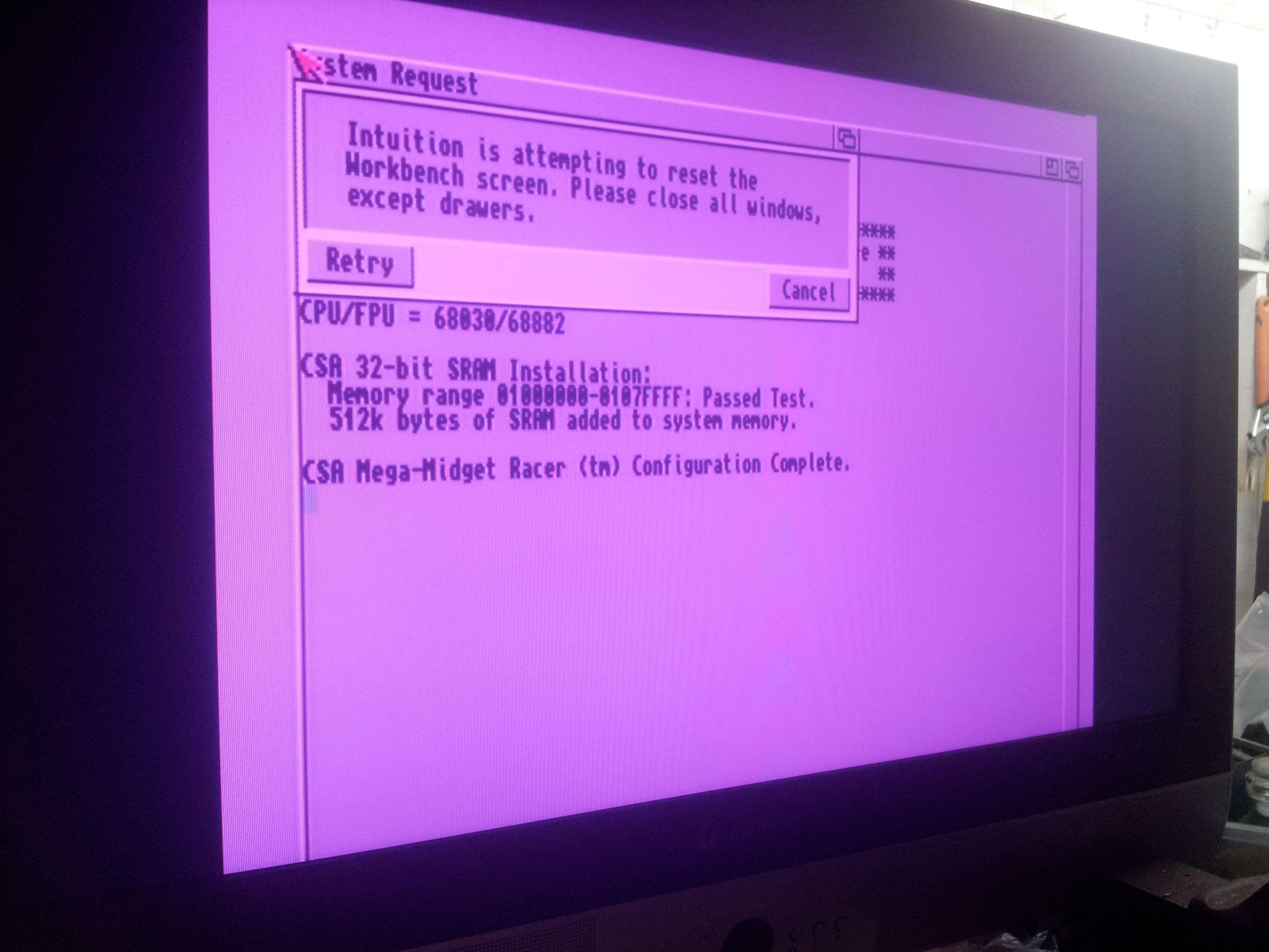 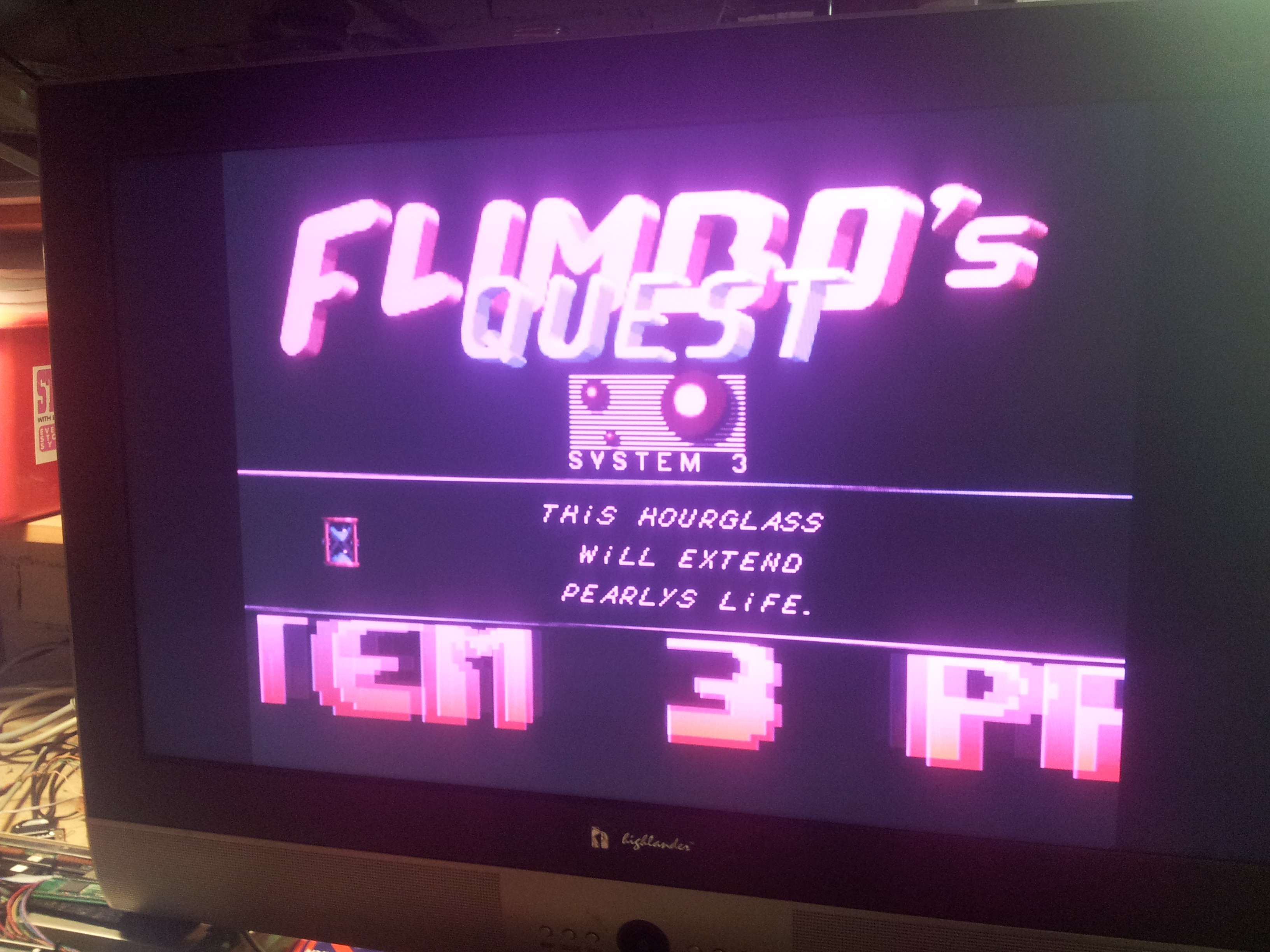 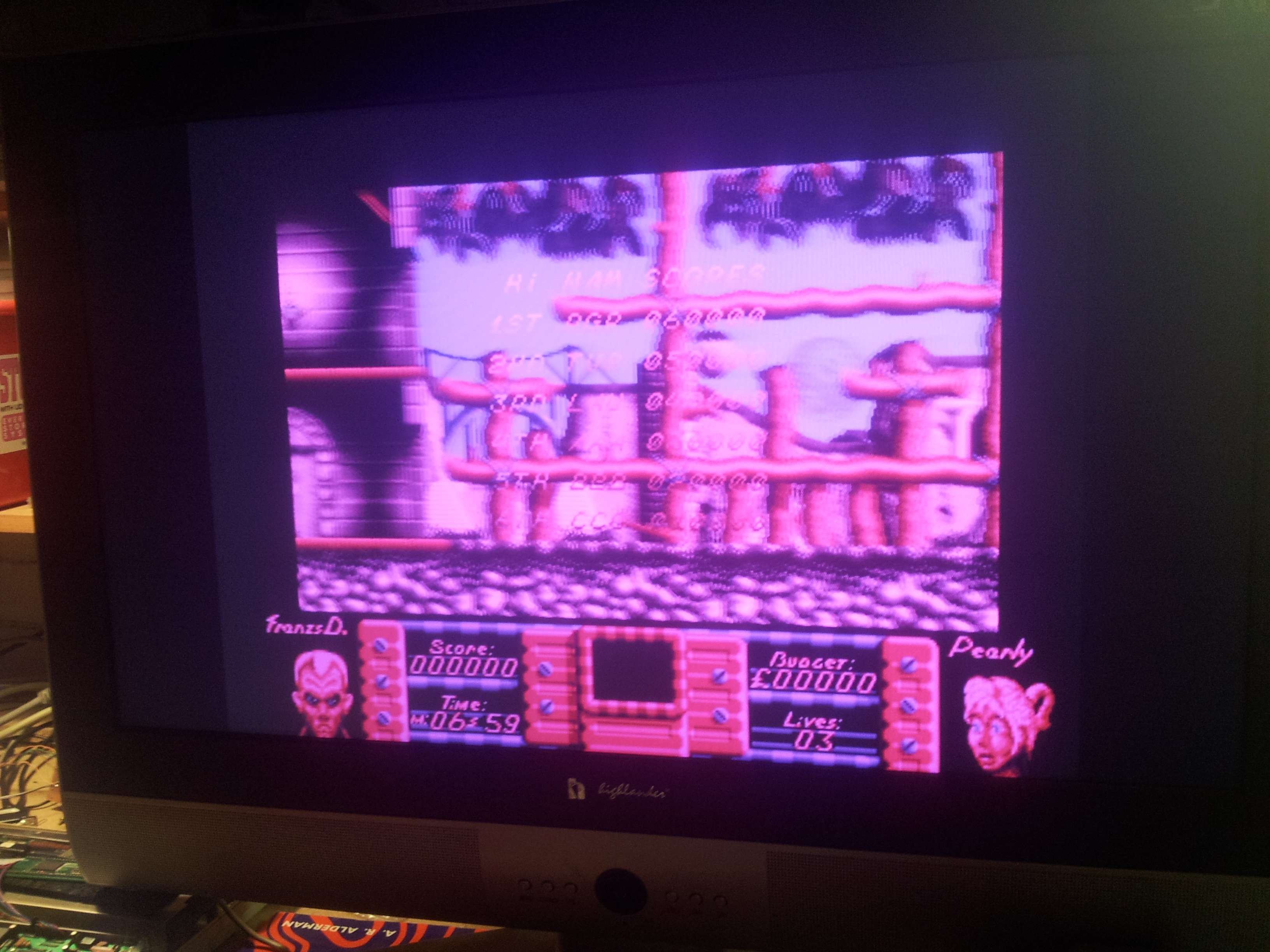 There is absolutely no green whatsoever!? and a seemingly excessive amount of red... it appears I had more green when using an opamp that didn't even suit video... although I couldn't actually read anything on the screen... xD 
|
|
|
|
22 November 2012, 03:15
|
#43 |
|
Registered User
Join Date: Nov 2012
Location: Adelaide, Australia
Posts: 57
|
Should I be adjusting R18 and R19?
|
|
|
|
22 November 2012, 16:09
|
#44 | |
|
Registered User
Join Date: Sep 2006
Location: Thunder Bay, Canada
Posts: 4,323
|
Quote:
http://www.linear.com/product/LT6551 Last edited by kipper2k; 22 November 2012 at 17:20. |
|
|
|
|
22 November 2012, 23:03
|
#45 |
|
Registered User
Join Date: Jan 2008
Location: United Kingdom
Age: 46
Posts: 733
|
@Amojammo
The Green video signal from the Amiga is not being fed into the adaptor properly. A pinkish screen is caused by a lack of green in the Y component of the video and CrCb being near their maximums. Check your wiring. Ian |
|
|
|
23 November 2012, 00:10
|
#46 |
|
Registered User
Join Date: Nov 2012
Location: Adelaide, Australia
Posts: 57
|
The circuit appears to have been assembled as per the schematic... should I perhaps replace R6/R7 with a potentiometer?
|
|
|
|
23 November 2012, 00:54
|
#47 | |
|
Registered User
Join Date: Sep 2006
Location: Thunder Bay, Canada
Posts: 4,323
|
Quote:
|
|
|
|
|
24 November 2012, 04:47
|
#48 |
|
Registered User
Join Date: Nov 2012
Location: Adelaide, Australia
Posts: 57
|
I've tried replacing:
R16 R17 R18 R19 R20 R21 R29 with potentiometers, generally two at a time...not one single modification gave me ANY green, other than perhaps what my brain was telling me was meant to be green... |
|
|
|
24 November 2012, 05:08
|
#49 |
|
Registered User
Join Date: Nov 2012
Location: Adelaide, Australia
Posts: 57
|
I found the "Colour Wheel" thing in workbench... which confused me, as I was fairly sure there was meant to be some green in there?
This is with the LT1254CN Opamp: http://www.datasheetcatalog.org/data...ogy/lt1253.pdf Pinout on page 2! 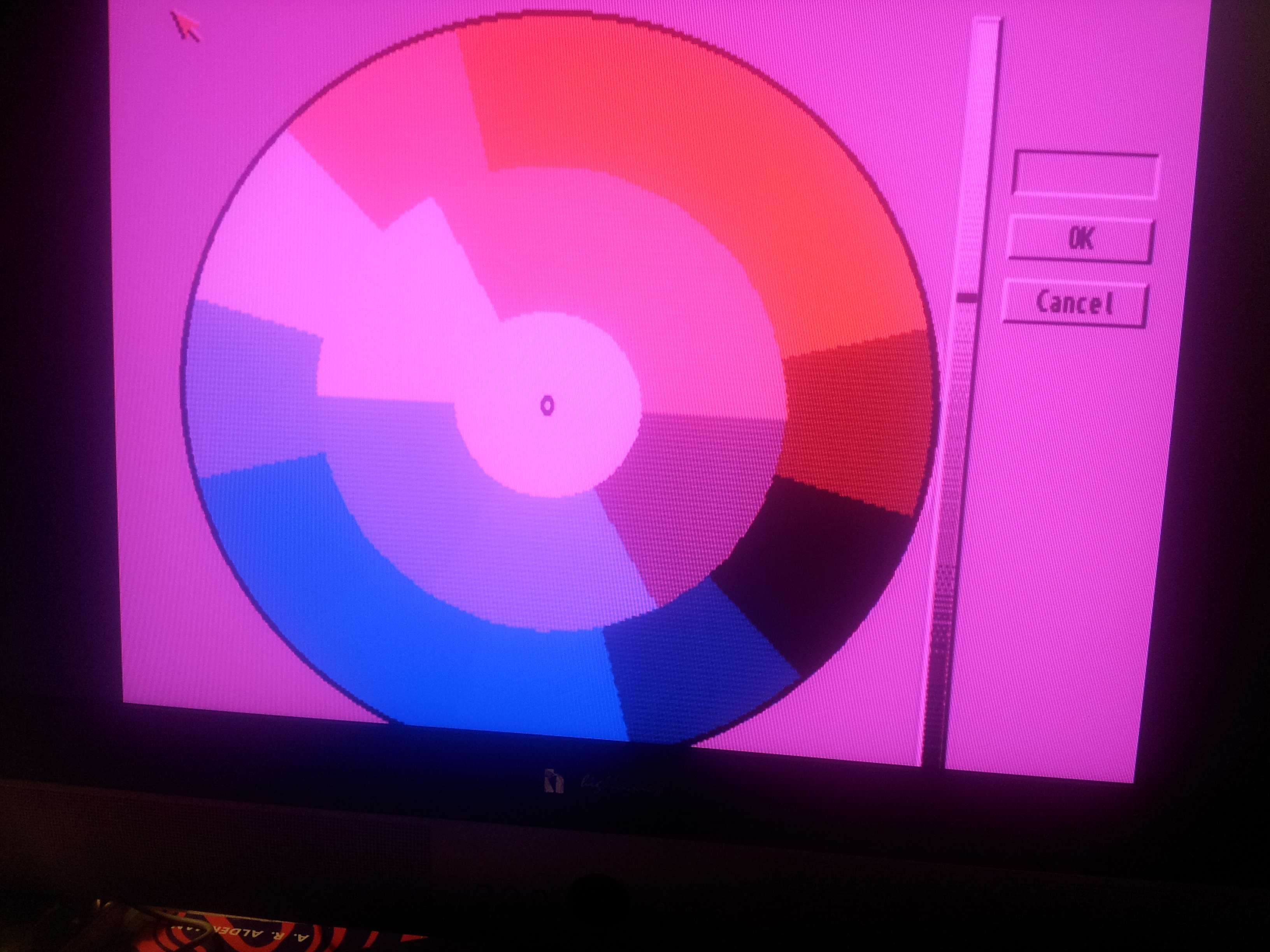 So I plugged my LCD monitor back in, which has a GBS8200 built in to the base... ah yes, green... so my circuit is displaying green as red, blue, black, and purple! as well as combining multiple shades of every other colour into one colour!  So, I then plugged the TL074CN opamp in to the circuit, which lacks the bandwidth required to display a proper image, date sheet found here, I believe the pinouts are THE same, and I've checked it four times now! http://ampslab.com/PDF/tl074cn.pdf and was greeted by this: 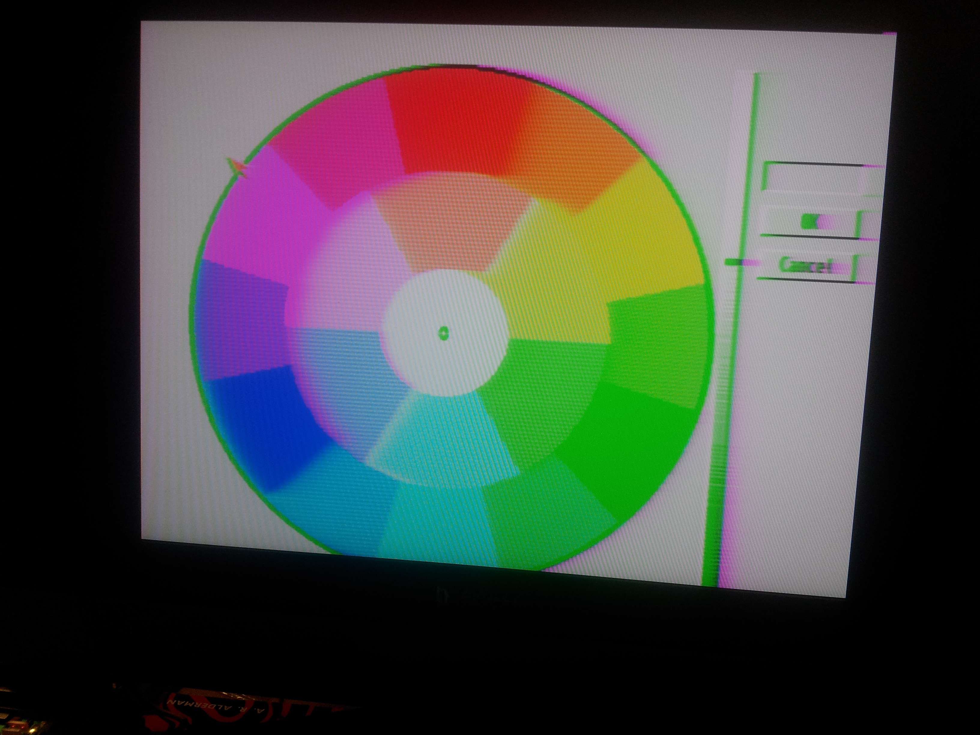 yes, it does display black as bright green... but at least it displays green?!?! Faults LT1254? I've tried two different ICs, and they give identical results.... I think I'll order/find some different opamps, and see what happens... but can anyone explain whats going on?!? |
|
|
|
24 November 2012, 05:41
|
#50 |
|
Registered User
Join Date: Nov 2012
Location: Adelaide, Australia
Posts: 57
|
I found that the -12volt from the Amiga video socket was dropping to -10.7volts with the load from the opamp...
Thinking this could be the issue, I wired up a little +12volt to +-12volt module, now I have identical +-12volt rails.. but no difference to the video... |
|
|
|
24 November 2012, 07:14
|
#51 |
|
Registered User
Join Date: Nov 2012
Location: Adelaide, Australia
Posts: 57
|
The EL2045 opamps originally used in this circuit are VOLTAGE FEEDBACK... while the TL1253 (and even the LMH6722 suggested earlier on) are CURRENT FEEDBACK!
they're completely different! and it explains why the TL074 gives correct colours, as it's also voltage feedback... |
|
|
|
04 January 2013, 09:11
|
#52 |
|
Registered User
Join Date: Aug 2012
Location: Melbourne, Australia
Posts: 888
|
How's your adapter going AJ, any more progress?
|
|
|
|
04 January 2013, 09:46
|
#53 | |
|
Unregistered User
Join Date: Sep 2012
Location: Copenhagen / DK
Age: 43
Posts: 4,190
|
Quote:
|
|
|
|
|
11 January 2013, 23:36
|
#54 |
|
Registered User
Join Date: Nov 2012
Location: Adelaide, Australia
Posts: 57
|
Havent touched it.
One day I'll get around to redesigning it for these different opamps. |
|
|
|
03 February 2013, 03:49
|
#55 |
|
Registered User
Join Date: Nov 2012
Location: Adelaide, Australia
Posts: 57
|
I dont suppose anyone could offer some input as to how to calculate the correct resistors? :P
|
|
|
|
03 February 2013, 05:45
|
#56 |
|
Registered User
Join Date: Nov 2012
Location: Adelaide, Australia
Posts: 57
|
Adjusting R6/R7 gave it green, I added a 10k pot in parallel, but its a very fine line between right and wrong...
adjust the pot too low, there's no green.... but adjust it too high, and there's still no green! Adjusting R4/R5 and R8/R9 make no difference, and the white still has a pink hue... I'll be honest, I'm very impatient, I spent some time trying to find out how to set the gain of current feedback op amps.. but my brain just can't do it   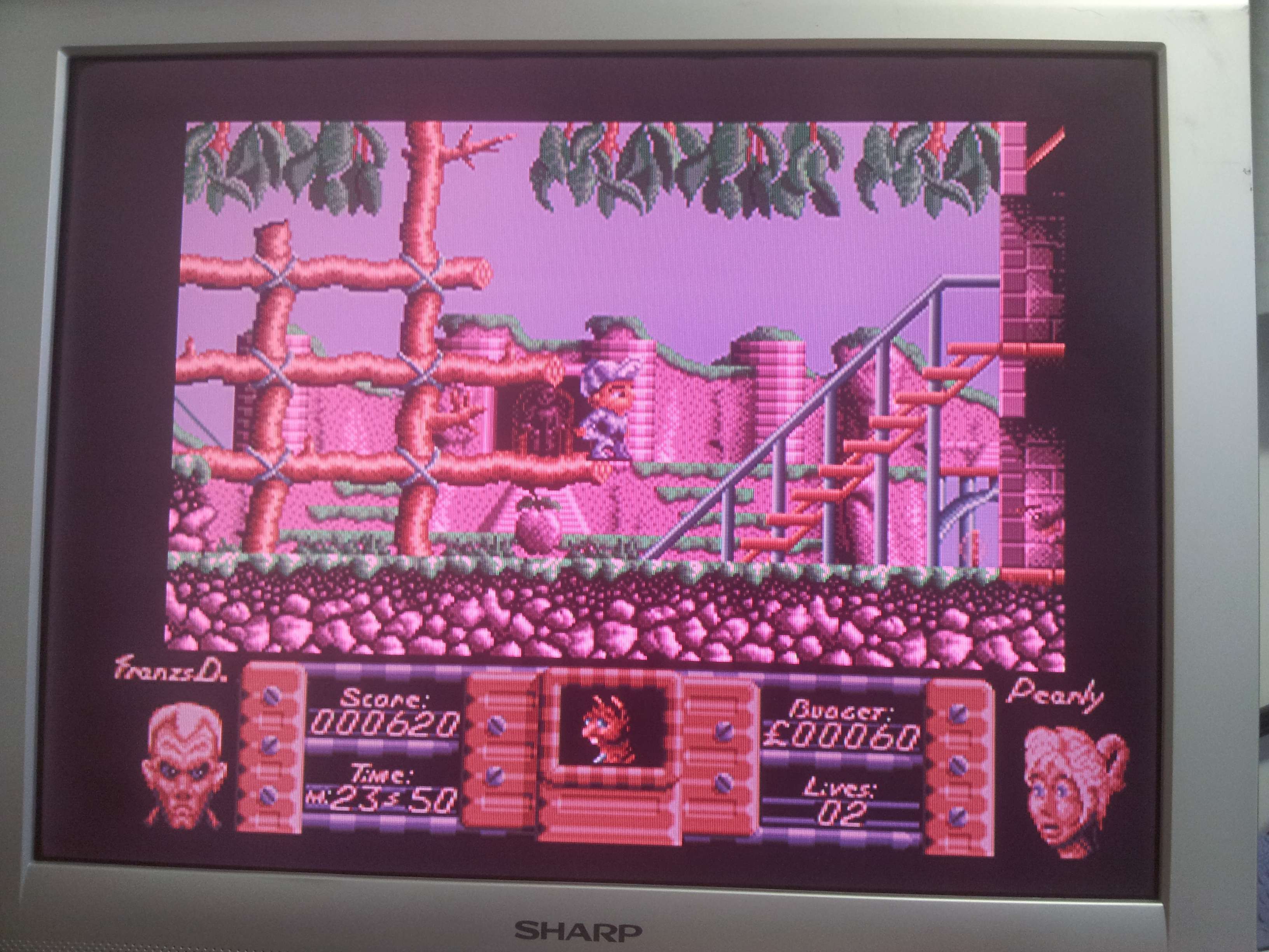
|
|
|
|
03 February 2013, 13:09
|
#57 |
|
Unregistered User
Join Date: Sep 2012
Location: Copenhagen / DK
Age: 43
Posts: 4,190
|
The gain is set the same way for current FB opamps as it is for voltage FB opamps, however you have to add a series resistor (typically around 100-500 ohms, look in the data sheet of the opamp for examples) to the input pin. Any capacitance on an input pin will cause it to oscillate, practically disabling it.
|
|
|
|
03 February 2013, 23:41
|
#58 |
|
Registered User
Join Date: Nov 2012
Location: Adelaide, Australia
Posts: 57
|
pin 3 and pin 5?
|
|
|
|
04 February 2013, 05:39
|
#59 |
|
Registered User
Join Date: Nov 2012
Location: Adelaide, Australia
Posts: 57
|
R22/23 were able to be adjusted to removed the red hue, but by the time the red hue is gone, so is most of the red
|
|
|
|
04 February 2013, 09:55
|
#60 |
|
Unregistered User
Join Date: Sep 2012
Location: Copenhagen / DK
Age: 43
Posts: 4,190
|
Which schematic are you using?
|
|
|
| Currently Active Users Viewing This Thread: 1 (0 members and 1 guests) | |
| Thread Tools | |
 Similar Threads
|
||||
| Thread | Thread Starter | Forum | Replies | Last Post |
| .WAV to RAW convertor? | Lonewolf10 | request.Music | 15 | 29 September 2012 21:37 |
| composite TV to VGA convertor | gizmomelb | MarketPlace | 0 | 25 January 2006 02:59 |
| Kefrons Convertor V1.35 (K2+) | redblade | request.Apps | 5 | 23 October 2004 01:08 |
| Joystick convertor idea! | ElectroBlaster | support.Hardware | 11 | 22 July 2003 13:38 |
| Amiga RGB to Svhs? | ElectroBlaster | support.Hardware | 12 | 12 December 2002 06:07 |
|
|


