
|
 10 June 2012, 18:28
|
#1 |
|
Ruler of the Universe
Join Date: Mar 2010
Location: Lanzarote/Spain
Posts: 6,195
 |
A1200 2B mb. Timing Fix, Indi MKII and others.
Hi:
After trying for some days my 2B mobo using a Fast Ata MKII, ACA1230/56 and the Indi MKII, I've decided that I've got to try the Timing Fix, as I was having problems with some screen modes, but also from time ago "blockid errors" that I can't fix. Well: I'll be following Ian's guide for the timing fix: http://www.ianstedman.co.uk/Amiga/am..._mobo_fix.html To start I've desoldered E123C and E125C:  Using chipquik is very fast and easy. Then I've soldered the Clockport to Paula wire link (REV 2B only): This is his original photo:  And this is mine:  Then I've done the U8 8520 CIA Wire link (REV 2B Only) This is his photo:  And this is mine:  Now I need to make two things from his web: Resistor added by ROMs (REV 2B Only): His photo:  I've bought this 470R, but it's carbon, I didn't find metal film: http://www.ebay.es/itm/290549067473?ssPageName=STRK:MEWNX:IT&_trksid=p3984.m1439.l2649 Edit: Ok I've bought also metal film: http://www.ebay.es/itm/270967459679?...84.m1439.l2649 , but it seems he used carbon ones (by the colors). I don't know, but I think it's better metal film ones: http://www.aikenamps.com/ResistorNoise.htm "Conclusions: In general, for low-noise design: Keep resistance values low, because thermal noise is directly proportional to resistance value. Wirewound resistors are the best choice for noise, followed by metal film, metal oxide, carbon film, and lastly, carbon composition. However, wirewound resistors are not readily available in large resistance values, and are usually inductive, which can cause instability problems in some cases. " Finally to change R118 to 220R I've bought this resistor: http://www.ebay.es/itm/250999177821?...84.m1439.l2649 (metal film), although I've seen also smd ones in different sizes: 0603: http://www.ebay.es/itm/100-SMD-SMT-0...item4166a61a60 or 0805: http://www.ebay.es/itm/100-x-SMD-SMT...item4166bb76ad I don't know if I can use them and what size. My R118 has 2mm. Please tell me if I've bought or done anything wrong. I REALLY think I'm mistaked. Just by the colors (Edit: It seems metal and carbon ones have different colors?¿) Last edited by Retrofan; 13 June 2012 at 23:10. |

|
|
11 June 2012, 12:51
|
#2 |
|
Ruler of the Universe
Join Date: Mar 2010
Location: Lanzarote/Spain
Posts: 6,195
|
Well I had a 470R resistor in my 1A mobo (for spares). The thing is that in Ian's photo I can't see very well where is he soldering it.
I've done this: Edit: Btw Ian, if you read this and you like the photo, you can use it.  This is his photo: Please somebody tell me if it's ok. Edit I was asking the pinout of Alice, to search for continuity in pin 43, but I would be getting surely continuity in several of them. Last edited by Retrofan; 20 June 2012 at 01:46. |
|
|
|
11 June 2012, 13:16
|
#3 |
|
Registered User
Join Date: Apr 2011
Location: birmingham
Age: 55
Posts: 2,827
|
looks good to me,all the custom chips are marked with a pin 1 and i think you just count round clockwise until you get to the one you want.
|
|
|
|
11 June 2012, 14:42
|
#4 |
|
PSPUAE DEV
Join Date: Nov 2006
Location: Wales / UK
Age: 45
Posts: 6,023
 |
@Retrofan,
The spot on the chip is pin 1, you then count Anti-clockwise around the chip. |
|
|
|
11 June 2012, 15:10
|
#5 | |
|
Registered User
Join Date: Apr 2011
Location: birmingham
Age: 55
Posts: 2,827
|
Quote:
yep,doh my bad |
|
|
|
|
11 June 2012, 15:11
|
#6 |
|
Ruler of the Universe
Join Date: Mar 2010
Location: Lanzarote/Spain
Posts: 6,195
|
Yep, I think you're right:
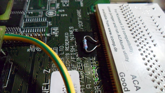
 But I wasn't having continuity with pin 43 of Alice. It's the other hole beside it (it has). I will solder it again now. (Edit: I was looking the wrong pin with a wrong image)- Ian's web: "The connection to C6B (brown SMT capacitor) is to pick up +5V. The resistor that has been added is a 470 Ohm, 0.25W resistor that then connects to DRA0 (DRAM address bus bit 0) by a PCB via. The timing modifications below state you should connect a 470 Ohm resistor from +5V to pin 43 of Alice, this modification does the same thing." Last edited by Retrofan; 14 June 2012 at 20:08. |
|
|
|
11 June 2012, 15:14
|
#7 |
|
PSPUAE DEV
Join Date: Nov 2006
Location: Wales / UK
Age: 45
Posts: 6,023
|
 , As I said in my warning. , As I said in my warning.I knew there were two holes. Bloody nightmare, .Do as I do and check a few time, just to make sure you have'nt counted the pins out wrong. |
|
|
|
11 June 2012, 15:26
|
#8 | |
|
Ruler of the Universe
Join Date: Mar 2010
Location: Lanzarote/Spain
Posts: 6,195
|
Ups! Sorry my photo isn't good, as Alice has more pins. I'll delete it and will search for another and will look where do I need the continuity.
Edited, now the photo is right. Well, I think it's ok in the first place I had soldered it (now it's unsoldered), but I have continuity in a couple of different holes, as I was supossing (just inserting the pin of the multimeter there and in pin 43). I will solder again to the first one. Edit: Ok, I've soldered again like in my previous photo. I've got continuity with pin 43 of Alice, although it's true that other hole also has it (nothing that I have done, of course). In fact in the 1A mobo I've tried and it has a lot of holes there with continuity with pin 43 too. So, I hope I've used the right one just for Ian's photo. Edit: I coudn't be really sure about the continuity (I mean, if the resistor was well soldered). Why? Because the smd on the other side of where I solder it also has continuity with pin 43. So I've desoldered from that part and now I'm sure that the resistor at least is well soldered as it has continuity. Now only remains to get and solder the 220R. I don't think I'll need to make Jen's 1K Fix. Anyway I'll copy here his post for if I have to use it: Quote:
Perhaps I'll have to solder again E123C and E125C. I will see. Last edited by Retrofan; 11 June 2012 at 20:02. |
|
|
|
|
13 June 2012, 15:21
|
#9 |
|
Ruler of the Universe
Join Date: Mar 2010
Location: Lanzarote/Spain
Posts: 6,195
|
Well, I've bought a 220R, 1/4w resistor in a local shop, and I've soldered it:
 Btw: This is how Ian did it:  Now I've made all the mods in Ian's guide. I've booted the miggy and it boots just like before, no other ploblem added. Now I've got in on using HighGfx. Will have to see what happens in an hour, that was when I had the vertical bars. Anyway there's a thing which I still have: Moving the icon "Run", or the Bin, I get a black screen for a second. Anyway, as I said in other post, I do think this last problem will be fixed with IC's update. Will tell later if I don't have the bars that is what I want (appart of having a HD CF without blockid errors). BTW: I'm running the miggy now without any fan. Last edited by Retrofan; 14 June 2012 at 03:31. |
|
|
|
13 June 2012, 18:08
|
#10 |
|
Ruler of the Universe
Join Date: Mar 2010
Location: Lanzarote/Spain
Posts: 6,195
|
This is what has happened: I was running it for half an hour and it has gone to black
 . .Now it works, but the indi doesn't. As soon as I select HighGfx or Superplus I have no screen through Hdmi. I didn't touch the Indi, but now I've unplugged it and plugged again, but nothing. What has happened? Last edited by Retrofan; 13 June 2012 at 21:51. |
|
|
|
13 June 2012, 20:23
|
#11 |
|
Banned
Join Date: Jan 2010
Location: france
Posts: 932
|
I guess you don't have another motherboard to test if the Indi is ok ?
|
|
|
|
13 June 2012, 21:28
|
#12 | |
|
Ruler of the Universe
Join Date: Mar 2010
Location: Lanzarote/Spain
Posts: 6,195
|
Quote:
Yes, I do have (1D1) and I've just tried it now. Nothing. The same as the other. The miggy works perfect, but when selecting any Indi screen it goes to black screen. And I've taked it off and a chip under it gets too hot: XILINX. What do I think? It's just casuality that it has happened after the timing fix (and half an hour later), working without fan with HighGfx. The Amiga works perfect. It's just the Indi that had any problem from the beginning (the vertical bars that anybody else has and the screen to black moving icons)- I'm going to write to Vesalia now. Anyway I think I should send both (mb too). What do you think??? Last edited by Retrofan; 13 June 2012 at 22:05. |
|
|
|
|
13 June 2012, 22:11
|
#13 | |
|
Registered User
Join Date: Sep 2006
Location: Thunder Bay, Canada
Posts: 4,323
|
Quote:
|
|
|
|
|
13 June 2012, 22:19
|
#14 |
|
Ruler of the Universe
Join Date: Mar 2010
Location: Lanzarote/Spain
Posts: 6,195
|
Thanks for posting kipper2k. No, and I appreciate your advice, but I won't try to make it. Seeing the Indi so hot and not working I think the best will be to send it back.
Edit: What I've only tried apart of changing the mb is to use IC's adapter, but it's the same. Anyway, what do you think, do you believe that if the miggy is working fine the fix can have done any harm to the Indi, or that it was defective with those [ Show youtube player ]? Or the first video I did, but with dirty lens... [ Show youtube player ] Last edited by Retrofan; 14 June 2012 at 00:42. |
|
|
|
13 June 2012, 22:29
|
#15 |
|
Registered User
Join Date: Apr 2010
Location: Scotland
Posts: 523
|
Hi sorry that its not working hope you get the support needed and not have to wait to long to have it back up and running
|
|
|
|
13 June 2012, 22:31
|
#16 |
|
Registered User
Join Date: Apr 2011
Location: birmingham
Age: 55
Posts: 2,827
|
just send the indi back.
i hope you get it sorted out and it not broken. |
|
|
|
13 June 2012, 22:33
|
#17 | |
|
Registered User
Join Date: Sep 2006
Location: Thunder Bay, Canada
Posts: 4,323
|
Quote:
|
|
|
|
|
13 June 2012, 22:36
|
#18 | |
|
Ruler of the Universe
Join Date: Mar 2010
Location: Lanzarote/Spain
Posts: 6,195
|
Thanks DonAmiga. If you know me I don't mind to wait to have what I want. For example I had the Indi unopened just waiting for kipper's adapter:
Quote:
|
|
|
|
|
13 June 2012, 22:49
|
#19 |
|
Amibay Mod/Staff
Join Date: Jun 2010
Location: birmingham uk
Age: 48
Posts: 1,019
|
hi mate sorry to hear this, i hope it is somthing simple
|
|
|
|
13 June 2012, 22:52
|
#20 |
|
Ruler of the Universe
Join Date: Mar 2010
Location: Lanzarote/Spain
Posts: 6,195
|
Thanks to all of you, mates. A word of Jens would be appreciated too
 ... but he's working out for a week... ... but he's working out for a week...  . And I KNOW and can tell he has treated me really well with their Warranty and Support. . And I KNOW and can tell he has treated me really well with their Warranty and Support.Perhaps Fol could tell something, even more as it will be a job for Vesalia (... I wish I would had bought it to Amigakit -just 'cause they are here-, but I did the preorder 2 years ago...) -Another prove about that I don't mind to wait a little for what I want- . And Vesalia has given me an incredible good service in all I've bought in the past, so I think it will be the same now, as always has. When I had problems with the Delfina, it was Vesalia the one that solved them all (well, and IC in first place, of course). And then it was my mistake. Now I haven't done anything to the Indi. Last edited by Retrofan; 15 June 2012 at 00:50. |
|
|
| Currently Active Users Viewing This Thread: 1 (0 members and 1 guests) | |
| Thread Tools | |
 Similar Threads
|
||||
| Thread | Thread Starter | Forum | Replies | Last Post |
| A1200 Timing fix for my Escom Amiga? | manic23 | support.Hardware | 46 | 19 August 2014 12:38 |
| timing fix question ACA | trydowave | support.Hardware | 5 | 19 August 2013 18:21 |
| My A1200 with ACA1232/33 & Indi AGA MkII | fitzsteve | Hardware pics | 10 | 12 May 2013 12:43 |
| Amiga 4000, Indi MKII and Mediator 4000Di | jvdw007 | support.Hardware | 2 | 21 June 2012 00:40 |
| ACA1230 timing fix | bx20 | support.Hardware | 17 | 24 August 2011 09:58 |
|
|


 , as I can't try it without that.
