
|
 16 April 2012, 00:27
|
#1 |
|
Ruler of the Universe
Join Date: Mar 2010
Location: Lanzarote/Spain
Posts: 6,185
 |
A1200 1D1 Joystick problem
Hi:
I've just bought a 1D1 A1200 motherboard. I don't have it here to take any photo and I'll have to wait a week or so for that. Well, it has been very cheap because the seller has told me that "... there seems to be a problem with the joystick port it goes up down and left but not right otherwise everything else works ok ". I just would like to know where should I begin to search. By now I'm thinking in cleaning the joystick pins with sandpaper. For what I've read it can be a faulty Cia chip. How do I determine it? |

|
|
16 April 2012, 00:35
|
#2 |
|
Zone Friend
Join Date: Jun 2006
Location: Gargore
Age: 43
Posts: 17,789
|
How about broken joystick, not port?
|
|
|
|
16 April 2012, 00:38
|
#3 |
|
Ruler of the Universe
Join Date: Mar 2010
Location: Lanzarote/Spain
Posts: 6,185
|
I've thought about it too. I wish it was that, but the seller sells a lot of Amiga stuff, so...
Last edited by Retrofan; 16 April 2012 at 02:43. |
|
|
|
16 April 2012, 03:00
|
#4 |
|
Registered User
Join Date: Sep 2006
Location: Thunder Bay, Canada
Posts: 4,323
|
Check pin 4 on the joy port, see if you have continuity to the IC, follow the trace from the connector to the IC, if no continuity, then you have a bad trace/cold solder joint, if its good, the IC could be bad.
|
|
|
|
16 April 2012, 10:18
|
#5 | |
|
Ruler of the Universe
Join Date: Mar 2010
Location: Lanzarote/Spain
Posts: 6,185
|
Quote:
I've found this http://www.allpinouts.org/index.php/...ck_Amiga_9_pin to know which is pin 4. Last edited by Retrofan; 16 April 2012 at 11:19. |
|
|
|
|
16 April 2012, 13:36
|
#6 | |
|
Registered User
Join Date: Sep 2006
Location: Thunder Bay, Canada
Posts: 4,323
|
Quote:
|
|
|
|
|
16 April 2012, 15:08
|
#7 |
|
Ruler of the Universe
Join Date: Mar 2010
Location: Lanzarote/Spain
Posts: 6,185
|
If it's at the right angle part of the pin I think I will be able to solder it without extracting the joy port, and Pin 4 is in the accesible part. I will look how the pin is there. Thanks.
Edit: Thinking well, what you say has sense as inserting many times the joystick perhaps can make a pin to break or have a bad solder joint. I will look first better in the joy connector than in the traces. Last edited by Retrofan; 16 April 2012 at 22:28. |
|
|
|
26 April 2012, 11:05
|
#8 |
|
Ruler of the Universe
Join Date: Mar 2010
Location: Lanzarote/Spain
Posts: 6,185
|
Jeje. I knew I was doing right opening this thread with time.
I've just received it. Just to open the parcel, to look to the back of the board where you told me and...  Doesn't the soldering in pin 4 look a bit "rare"? Time for soldering. Edit: Done: 
Last edited by Retrofan; 26 April 2012 at 12:11. |
|
|
|
26 April 2012, 20:53
|
#9 |
|
Registered User
Join Date: Apr 2010
Location: Italy
Posts: 1,136
|
9876
12345 the square pin is number 1 |
|
|
|
26 April 2012, 23:22
|
#10 |
|
Ruler of the Universe
Join Date: Mar 2010
Location: Lanzarote/Spain
Posts: 6,185
|
You are right. I think I've soldered pin 7. Well, anyway it was looking wrong. I haven't tried it yet, but I'll have to search again.
Edit: HEY! I don't have the cap in R370C, here it has it http://amiga.resource.cx/photos/phot...res=hi&lang=en I have a broken motherboard for spares, 1D4 I believe. Ah, I've tried it with it's 3.0 kickstarts, using an old Hd I had since I bought my Amiga and using a Hawk ramboard I have since then too, and it was working nice: keyboard, sound, games... but no right movement as said. (Edit: I think I didn't try fire in that game) Photo (edited): 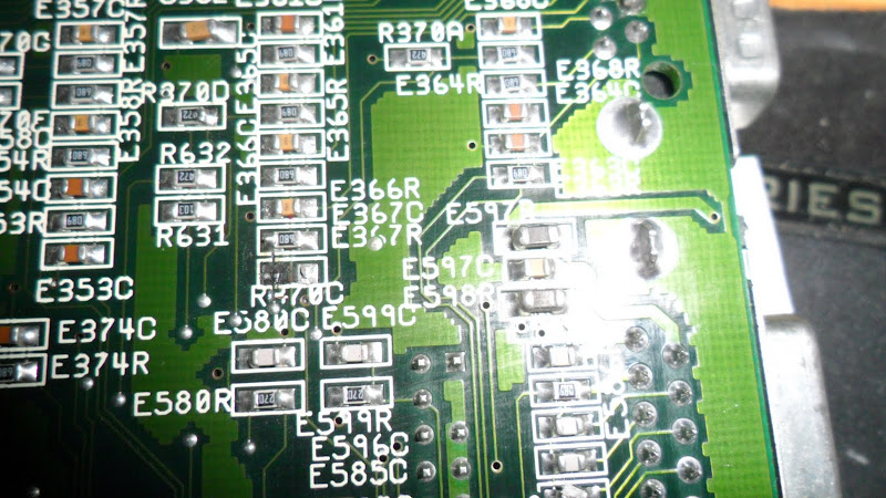 Edit: Better photo:  BTW: Is there an easy way to try the joystick without playing a game? Edit: I still think I'm lucky, as although it doesn't have the place to solder it on the left, I can solder a copper wire between the upper cap and the bottom solder point and solder the cap I need in it's place joined to that cable, if you don't tell me no. Edit again: I think I'll search first for continuity between both points and if it has I'll try to peel the trace where the left part of the cap goes and to solder there a drop, to use it to solder the cap. Edit: No, it hasn't continuity, but in my "for spares" mb it has... so I'll try to peel it anyway and solder that drop or if not I will use the copper wire. Edit: I still have some Chipquik to desolder the cap... Last edited by Retrofan; 28 April 2012 at 11:56. |
|
|
|
27 April 2012, 11:41
|
#11 |
|
Ruler of the Universe
Join Date: Mar 2010
Location: Lanzarote/Spain
Posts: 6,185
|
Ok I've made this joining them with a copper wire:
 But still I don't have right in my joystick. It goes left without pressing left. I've got continuity across the cap and from the upper one to the bottom point. Edit: If it goes all the time to the left, perhaps isn't right the one that's wrong, but left I'm thinking. EDIT: 1R0 in the middle of my photo is the way round compared to the image of hardware resource http://amiga.resource.cx/photos/phot...es=hi&lang=en: 
Last edited by Retrofan; 27 April 2012 at 14:23. |
|
|
|
27 April 2012, 12:36
|
#12 |
|
PSPUAE DEV
Join Date: Nov 2006
Location: Wales / UK
Age: 45
Posts: 5,999
 |
With Ceramic caps and resistors. It doesnt matter which way round they go.
Only if they are polarised, do you need make sure they are in the correct way around. I had a problem like that before, it turned out to me a component on the bottom of the board. I also have had one with dry joints causing the array to read the wrong value and cause all sorts of odd movements. Take a look at the schematics and look every where, where the components are, where they go to, then check all track. You generally cant check caps in circuit, as you could end up reading other parts of the circuit. |
|
|
|
27 April 2012, 14:09
|
#13 |
|
Ruler of the Universe
Join Date: Mar 2010
Location: Lanzarote/Spain
Posts: 6,185
|
Thanks Fol. Well in fact I've turned it, but it's the same.
BTW: This is completely wrong, isn't it?  The clockport must be on the right, musn't it? If I connect a Delfina there I would fry it like it happened to Gibs. |
|
|
|
27 April 2012, 14:28
|
#14 | |
|
Registered User
Join Date: Dec 2010
Location: Norway
Posts: 817
|
My a600 had a joystick stuck to the left, where the fault was the U34.
There are several threads about joystick stuck up or left problems. Do all directions work in the mouse port? Here are some nice troubleshooting tips from Toni Wilen from another thread: Quote:
|
|
|
|
|
27 April 2012, 14:44
|
#15 | ||
|
PSPUAE DEV
Join Date: Nov 2006
Location: Wales / UK
Age: 45
Posts: 5,999
|
Quote:
Quote:
|
||
|
|
|
27 April 2012, 15:04
|
#16 |
|
Ruler of the Universe
Join Date: Mar 2010
Location: Lanzarote/Spain
Posts: 6,185
|
Thanks both. In fact fgh you've given me very good tips.
The mouse goes perfect. So U34, eh? Edit: Oh, it was to try the joystick in the mouse port... Well, too late... Well... let's see what I'll do now...  EDIT: Don't know why, but this seems a nice place to solder that piece... humm...  Edit: Well, it looks good:  Now just to try it, but later. Last edited by Retrofan; 27 April 2012 at 16:15. |
|
|
|
27 April 2012, 19:06
|
#17 |
|
Ruler of the Universe
Join Date: Mar 2010
Location: Lanzarote/Spain
Posts: 6,185
|
Well, to all the interested people.... IT WORKS !!!
Jeje... I've got a fully working 1D1 mb for 20 pounds and I've had a lot of fun repairing it. Thanks to all and to Chipquik in particular  . .Now to add the pins to the clockport  Edit: Done.  Thanks Airey36 because you searched that mb for me, you told me the problems and you offered me a good price. Last edited by Retrofan; 27 April 2012 at 22:53. |
|
|
|
27 April 2012, 23:52
|
#18 |
|
PSPUAE DEV
Join Date: Nov 2006
Location: Wales / UK
Age: 45
Posts: 5,999
|
You need to cut two pins off the clock port so you can fit the clockport cable on.
Just make sure you cut correct ones. Also remember the delfina red wire is opposite compared to subway. http://www.amigakit.co.uk/support/delfina.php |
|
|
|
28 April 2012, 00:07
|
#19 |
|
Ruler of the Universe
Join Date: Mar 2010
Location: Lanzarote/Spain
Posts: 6,185
|
Ok. I just will desolder them or all of the unnecesary ones.
Edit: And I'm wondering why did they put it on the left, marking clearly Pin 1, that is also printed in the mb. I'm remembering Jens saying "THERE IS NO PIN 1 ON A CLOCKPORT. Numbering starts at 19, ant it ends at 40. Only refer to pictures for correct orientation of the red marker of the clockport cable. Any marker of a "pin 1" on the clockport is plain wrong. The clockport is a *part* of a 40-pin row, and it happens to be the upper half plus two pins. Still, numbers don't change. Only definitions of "where to put the red marker" can change. I use "red marker on 40" and Michael from E3B uses "red marker on 19". These are not to be confused." In the other 1D1 Mb the clockport pins are on the right, but here, the same revision, are on the left. Now I completely understand Gibs. Another thing: I left the other pins because I saw this photo http://amiga.resource.cx/photos/phot...es=hi&lang=en: So in that mb you coudn't install the clockport cable either. Edit: Changed. Now only on the right. 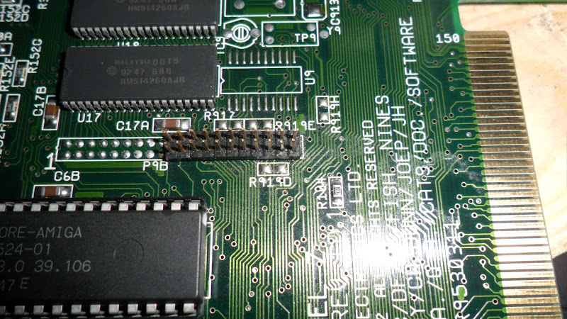 Edit: And just to finish: Mounting this mb with the Ide Hd (420 Mb), 3.0 kickstarts and the Hawk ramboard has made me wish to mount another Amiga just with this. I'll like to have it like the previous owner had it and sold to me. That was my first A1200, that now has a BPPC and a lot of stuff. Last edited by Retrofan; 02 June 2012 at 21:42. |
|
|
| Currently Active Users Viewing This Thread: 1 (0 members and 1 guests) | |
| Thread Tools | |
 Similar Threads
|
||||
| Thread | Thread Starter | Forum | Replies | Last Post |
| AMIGA A1200 Joystick Port Problem, Please Help ? | Rich M | support.Hardware | 18 | 28 August 2014 10:40 |
| Need SMD resistor values (A1200 1D1) | 8bitbubsy | support.Hardware | 1 | 13 December 2010 08:35 |
| WANTED: A1200 1d1 motherboard | Wasagi | MarketPlace | 2 | 18 August 2010 20:58 |
| WANTED: 1d1 Amiga 1200 or 1d1 motherboard | Wasagi | MarketPlace | 0 | 16 August 2010 01:11 |
| FOR SALE: A1200 Desktop (1D1) Plus PSU and Mouse | Peter | MarketPlace | 17 | 29 July 2010 23:33 |
|
|


