|
 26 February 2015, 04:13
|
#581 |
|
Registered User
Join Date: Aug 2012
Location: Melbourne, Australia
Posts: 888
|
Yep, guilty as charged!

|

|
|
26 February 2015, 04:34
|
#582 | |
|
Registered User
Join Date: Aug 2011
Location: Omnicorp
Age: 45
Posts: 5,813
|
Quote:
|
|
|
|
|
26 February 2015, 04:58
|
#583 | |
|
Registered User
Join Date: Aug 2012
Location: Melbourne, Australia
Posts: 888
|
Quote:

|
|
|
|
|
30 March 2015, 11:48
|
#584 |
|
Registered User
Join Date: Aug 2013
Location: Croatia
Age: 43
Posts: 341
|
Just stumbled upon this and rememberd "voes by prolific" some people have. This may help, apparently there are drivers for fake prolific chips that work on Win7 32/64, maybe flashing would work with them
 http://nerdralph.blogspot.in/2013/09...tl-serial.html |
|
|
|
31 March 2015, 23:51
|
#585 | |
|
Registered User
Join Date: Feb 2012
Location: United Kingdom
Posts: 3,173
|
Quote:
|
|
|
|
|
01 April 2015, 10:29
|
#586 |
|
Registered User
Join Date: Aug 2013
Location: Croatia
Age: 43
Posts: 341
|
I'm glad it's useful to someone
. Original version should work for most people, other two versions were tries to get it to work with kipper2k's 8MB CF board. For me (somewhat odd configuration, A500 rev8a, modded to A500+ 1MB chip ram + 512kB expansion, that gets added to chip since it works as a500+) it worked on and off so I tried to specify memory locations to load kickstart in case mkick sometimes borked this by itself. But it didn't make difference. On vanilla A500 (512 chip / 512 fast) it worked without issues for some reason.
|
|
|
|
01 April 2015, 20:57
|
#587 | |
|
Registered User
Join Date: Feb 2012
Location: United Kingdom
Posts: 3,173
|
Quote:
|
|
|
|
|
18 May 2015, 17:51
|
#588 | |
|
Registered User

Join Date: Oct 2009
Location: Italy
Age: 45
Posts: 196
|
Quote:
|
|
|
|
|
19 May 2015, 04:15
|
#589 | |
|
Registered User
Join Date: Sep 2006
Location: Thunder Bay, Canada
Posts: 4,323
|
Quote:
https://www.fairchildsemi.com/datasheets/BC/BC547.pdf I will have pictures hopefully very soon on 2 new floppy emulators |
|
|
|
|
19 May 2015, 09:37
|
#590 | |
|
Registered User
Join Date: Sep 2008
Location: Paris / France
Posts: 656
|
Quote:
By this way you don't have to drawn current from the open collector floppy bus and make the thing unreliable... |
|
|
|
|
15 June 2015, 20:08
|
#591 | |
|
Registered User
Join Date: Oct 2009
Location: Italy
Age: 45
Posts: 196
|
Quote:
http://www.ebay.com/itm/3-Keys-Black...item3f4db8ef01 |
|
|
|
|
21 July 2015, 18:07
|
#592 |
|
Registered User
Join Date: Aug 2013
Location: Croatia
Age: 43
Posts: 341
|
Oops, have't seen this post.
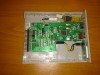
I think it wouldn't work (at least with current IR receiver firmware). It doesn't say what kind of remote it is. It could be made to work with it, but first you'd need to record codes it sends and then add them to the firmware. Not really hard, but you'd need arduino board. This is the remote I used, here are two, only difference is color, one is white, the other one is black http://www.ebay.com/itm/181376306618 http://www.ebay.com/itm/331439837335 Thing is they're universal remotes that cycle through supported codes while you keep mute button pressed. My firmware "listens" for these codes and when it recieves mute code it recognizes it blinks it's led to let you know remote is on correct IR code set. Other remotes might work, but depending on the way they cycle through codes it could be harder to tune it. I hardcoded 4 code sets (2 + 2, sets switchable via jumper), one of them should correspond to LG remotes and the other to Sony remotes (other two I don't know, I had these TV's so I know they reacted along with GOTEK). So if you set your remote to Sony or LG codes it might work. |
|
|
|
17 August 2015, 21:02
|
#593 |
|
Registered User
Join Date: Oct 2009
Location: Salem, OR
Posts: 1,767
|
OK, question about framing/support..
(And no, I don't have a 3D printer.. ;-) So, I found out my issue with kickstart (apparently the method I was using to create ADFs wasn't a good one (they were old) and my kryoflux to ADF works; not sure what I did wrong before, but..), and I CAN boot my A1000 off of the Gotek!! Also, I found that if I take the Gotek out of its case, the USB and buttons fit nicely where the disk would go in, and the LCD fits nicely just outside that. But.. Right now, I have a rubber band and a few paperclips (on the outside of the case holding the rubber bands) holding the gotek board against the inside of the case. It's enough to know that it works and lines up nicely, but even I know rubber bands aren't the best long term solution.. ;-) I need to come up with some kind of frame to hold it in place, probably which lines up with the holes that held the old drive in place.. I've done some basic electronics, but not building guides to hold in cards.. So, thoughts on how I should proceed? I was thinking trying to use some plastic sticks (I can probably find something??) and super gluing them together? Or possibly thin metal strips bent into place? Is there something that works better/worse for custom frames for electronics??? Luckily, this is going inside a case, so I'm OK if it looks bad, but still would like it to survive my plugging in the USB stick.. Any help you could provide would be.. um.. er.. helpful.. ;-) Thanx, OK, this is what I have done:  And from the front, it looks like:  Yes, those are cut down plastic forks.. ;-) I didn't realize that they lined up as well as they did. I can add 2 more if I need to.. We'll see how stable it is... For the Gotek: Slot 1 is my kickwork boot disk that boots KS 1.3, then loads the RAM and IDE/CF drivers (tomthul models) and finishes the boot off of the CF card. Slot2 is a standard KS 1.3. I think slot 3 is a KS 1.3/WB1.3 floppy (no RAM/IDE drivers). Then I have a few games starting at slot 5. Don't want to put too many in there, as I won't remember what is in what slot. ;-) desiv Last edited by desiv; 18 August 2015 at 04:57. |
|
|
|
19 August 2015, 05:34
|
#594 |
|
Registered User
Join Date: Jun 2012
Location: Liverpool, UK
Posts: 17
|
Hey guys!
I did my own mod using a PNP darlington (MPSA63), a 1K resistor, a 1uF capacitor and a buzzer. This circuit is easier and works like a charm! 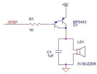 The buzzer I used is a SBT-12 https://www.westfloridacomponents.co...+SBT-1212.html but any buzzer 5V to 12V with any frequency should work. The peak generated by Gary is so tiny that it has to be stretched by the cap and a transistor with a large Beta or else, you can't hear it. Result really sound like a floppy! |
|
|
|
19 August 2015, 05:41
|
#595 | |
|
Registered User
Join Date: Aug 2012
Location: Melbourne, Australia
Posts: 888
|
Quote:
|
|
|
|
|
19 August 2015, 14:53
|
#596 |
|
Registered User
Join Date: Jun 2012
Location: Liverpool, UK
Posts: 17
|
Not entirely but the output waveform is more natural than only a pulse;
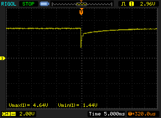 You can clearly see the two charging curves of both transistors in the darlington and the capacitor charge |
|
|
|
08 September 2015, 20:06
|
#597 | |
|
Posts: n/a
|
Quote:
|
|
|
09 September 2015, 10:54
|
#598 | |
|
Registered User
Join Date: Sep 2009
Location: Syd
Posts: 184
|
Quote:
|
|
|
|
|
24 October 2015, 11:49
|
#599 |
|
Registered User
Join Date: Feb 2014
Location: Maitland / AUSTRALIA
Posts: 205
|
Hi All,
Ive read the entire thread, and Googled with no direct answer... I have flashed numerous Goteks for the Amiga....and I have all manner of USB sticks and SD cards with USB adapters working fine, except this Sandisk Cruzer Fit 8GB. I have noted others saying this particular model works OK, and these were bought from a reputable Aussie retailer. I have cleaned it, reformatted it, tried different allocation sizes and numerous copies of SELECTOR.ADF...all to no avail. I put the USB stick in the Gotek, it flashes 000 then ---. I have tried 2 brand new sticks, both with the same issue. I have the same model in a 16Gb and it works perfectly. Of course in the PC they work perfectly. There is general mention of some sticks not being compatible with the Gotek...does anyone have any thoughts? |
|
|
|
24 October 2015, 17:53
|
#600 | |
|
Registered User
Join Date: May 2001
Location: ?
Posts: 19,645
|
Quote:
My iBook G4 also does NOT like that USB stick. I know it's super tempting to get it because of its ultra small profile (so it doesn't stick out of your AMiga much), but I bought two different ones and they have all given me trouble. I ended up using them where they worked: my Raspberry Pi and my XBox 360. |
|
|
|
| Currently Active Users Viewing This Thread: 1 (0 members and 1 guests) | |
| Thread Tools | |
 Similar Threads
|
||||
| Thread | Thread Starter | Forum | Replies | Last Post |
| Love Emulators? - Dgen & Hatari emulators | Paul | News | 18 | 14 January 2023 20:56 |
| Cd32 from analogic computers not working properly | fondpondforever | Amiga scene | 11 | 22 August 2013 14:24 |
| A1200 floppy not working | mtb | support.Hardware | 5 | 22 November 2010 09:05 |
| floppy df0 working / not working | Dave_wb | support.Hardware | 3 | 07 January 2009 09:11 |
| Guinness Book entry with 274 working Computers/Consoles | Retro-Nerd | Retrogaming General Discussion | 4 | 25 August 2007 19:56 |
|
|


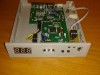
 . Here's how it looks, Arduino is used only as 5V power supply