
 |
|
|
#1 |
|
Registered User
Join Date: Jan 2010
Location: N/A
Posts: 873
|
Question about A1200 CDrom power supply
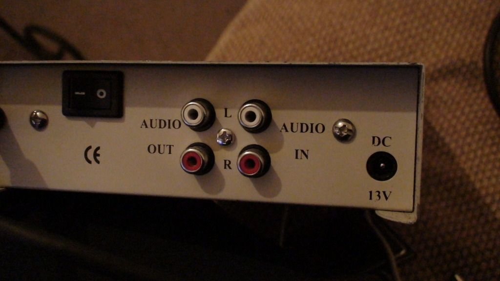
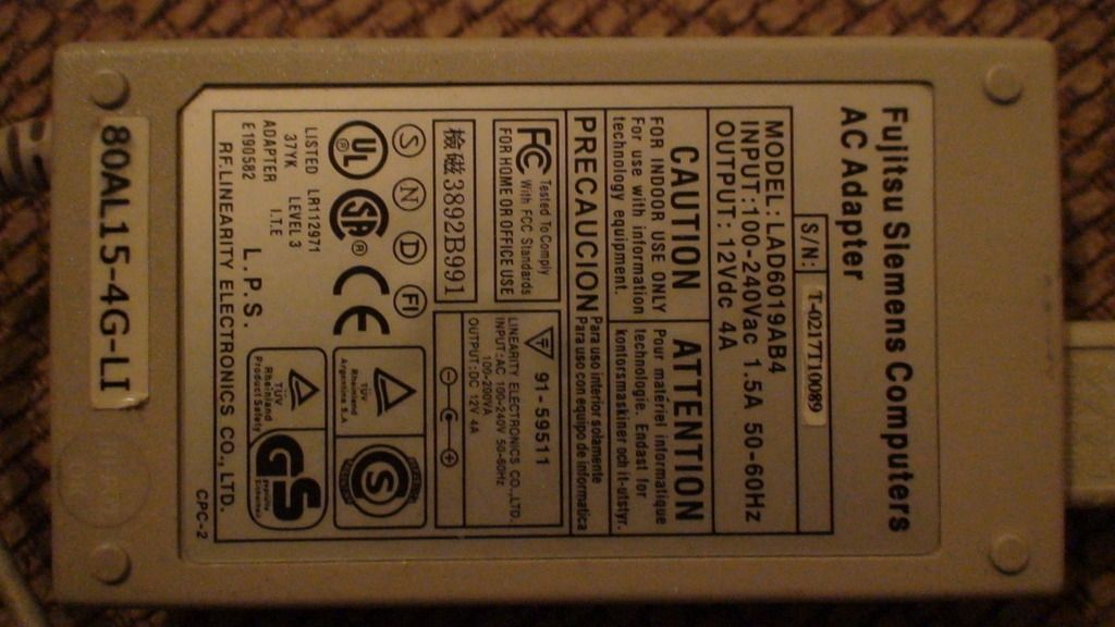
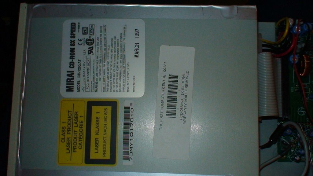
Recently got a CD rom drive for an A1200 but it doesn't have a power supply? I have a spare one for another device that i use with some external hdds with no problems. Would it be ok to use on this cdrom? Thanks
Last edited by trydowave; 10 May 2017 at 01:15. |
|
|
|
|
#2 |
|
Registered User
Join Date: Oct 2012
Location: South Shields
Posts: 812
|
You really need to know whether it needs centre positive or centre negative before you power it on (your power supply is centre positive). Get the wrong one and you will damage it, check for a sticker somewhere else on the cd case. It will look something like this: https://upload.wikimedia.org/wikiped...e-positive.svg But the on second look the voltages do not match either, maybe someone more familiar with electricity can help you here...
|
|
|
|
|
#3 |
|
Registered User
Join Date: Jan 2010
Location: N/A
Posts: 873
|
It seems like the cdrom needs more power than the brick is able to give. Im guessing the worst thing that could happen is that it just doesn't power on? Don't you think?
|
|
|
|
|
#4 |
|
Registered User
Join Date: Jun 2012
Location: Worksop/UK
Age: 59
Posts: 1,328
|
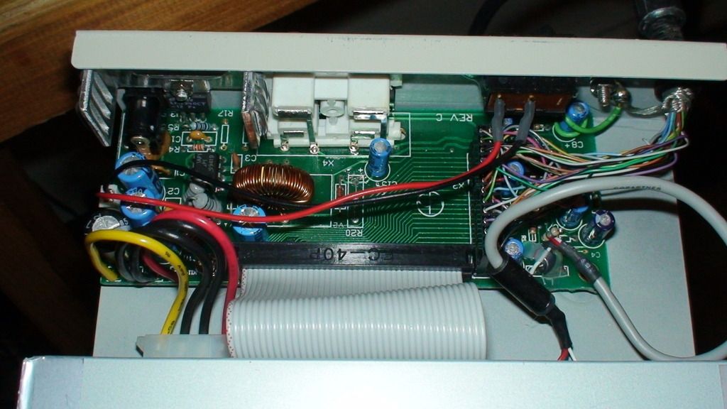
That 12v supply is more than adequate to run the cdrom, they run from 12v and 5v anyway. There is a regulator and smoothing circuit inside the cdrom case that would lower a 13v supply down to 12v anyway. But as already mentioned, make sure the centre pole of that power socket is wired to positive, you can't really tell from those pictures. My guess is it is but make sure first.
|
|
|
|
|
#5 |
|
Registered User
Join Date: Jan 2010
Location: N/A
Posts: 873
|
Ive looks inside again and theres no image depictiing the centre positive / centre negative. Near the molex it says Dc input. and then 5V G G 12V but im not sure that helps?
Looking for a manual or any information regarding this drive: A mirai cd rom 8x speed model icd-1200/AT. There's nothing. What would happen if it was the wrong one? A bang, killing the cd rom? or would it just not turn on? Cheers |
|
|
|
|
#6 |
|
Registered User
Join Date: Jun 2012
Location: Worksop/UK
Age: 59
Posts: 1,328
|
Easiest way to find out is with a multimeter, touch 1 probe to the centre pole and the other to positive then negative on the regulator board, or even on the molex to see which gives continuity. The 2 black wires on the molex are negative the other 2 are 12v and 5v.
It depends if the regulator board includes a protection circuit on what would happen with crossed polarity, IF it is protected it just wouldn't work, if it isn't you would fry the electronics on the board! EDIT: Looking at the pictures it doesn't look like there is any protection circuit there, unless there is some fuse-able type resistors or diodes that are hidden by those wires and can't be seen. You really need to test that centre pole with a multimeter or continuity tester to see if it's positive or negative before trying it. Last edited by ptyerman; 10 May 2017 at 01:58. |
|
|
|
|
#7 |
|
Registered User
Join Date: Jan 2010
Location: N/A
Posts: 873
|
What about this:
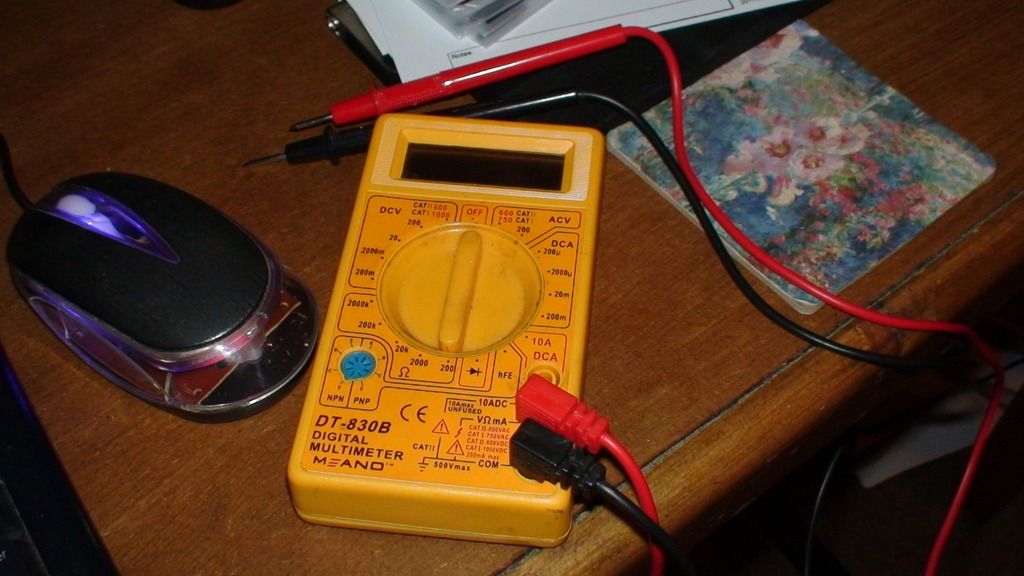 Things is.. im not sure how to use it. Where to turn the dial too (if i remember right its DCV 20?) and what parts to test. Not sure what the regulator board is. I know the pins on the molex. Any chance you could guide me please  Edit: i dont what im doing but i stuck the red pin into the yellow molex and the black in the red. I set the multimeter to 200k and it went from - to 165 to 180 fluctuating. Does that tell you anything? Last edited by trydowave; 10 May 2017 at 02:08. |
|
|
|
|
#8 |
|
Registered User
Join Date: Jun 2012
Location: Worksop/UK
Age: 59
Posts: 1,328
|
OK, at the bottom of the dial is a diode mark, turn the dial either to that or to the resistance scale next to it which is above the blue transistor test socket, if you choose the resistance scale turn it to 20k.
Looking at that photo of the cdrom you see 2 wires going from a white plug on the board to a on/off switch on the rear of the case, that switch will be inline with the positive circuit so use that to test with. Hold one probe on the centre pole of the input socket and the other probe on one of those two wires making sure the switch is in the on position. If your meter shows a continuity reading or gives out a beep then you know that the centre pole is connected to the switch and that it is wired positive. If not it means it is negative. |
|
|
|
|
#9 |
|
Registered User
Join Date: Jan 2010
Location: N/A
Posts: 873
|
no beeps but for a while when i connected black on the molex with the centre pin it went from 1 to 1960 or something like that. and when i tried yellow and cenre pin it was 6 something? Does that make any sense? It was set to 20k.
|
|
|
|
|
#10 |
|
Registered User
Join Date: Jun 2012
Location: Worksop/UK
Age: 59
Posts: 1,328
|
That could just be a reading from the in circuit components. Forget testing using the molex, it could give a false reading. Just use the white plug that the 2 wires come out of that go to the switch, with the switch in the on position either wire will give a reading if they are connected to the centre pole, if the switch is in the off position only one of those wires will read. If they give a reading that means they are connected to the centre pole and it will be positive.
|
|
|
|
|
#11 |
|
Registered User
Join Date: Jan 2010
Location: N/A
Posts: 873
|
Centre pole connected to both wires gives reading. One wire connected to centre pole give reading when off...
So its positive right? So everything will be alright as the adapters positive. |
|
|
|
|
#12 |
|
Registered User
Join Date: Jun 2012
Location: Worksop/UK
Age: 59
Posts: 1,328
|
Sorry mate, had a bit of sleep time so missed your post. Yes, that sounds good, plug it in and give it a try. That PSU is good enough to run it.

|
|
|
|
|
#13 |
|
Registered User
Join Date: Jan 2010
Location: N/A
Posts: 873
|
thanks everyone for the help. It works fine now.
|
|
|
| Currently Active Users Viewing This Thread: 1 (0 members and 1 guests) | |
| Thread Tools | |
 Similar Threads
|
||||
| Thread | Thread Starter | Forum | Replies | Last Post |
| Newbie with power supply question | sp8rky | New to Emulation or Amiga scene | 2 | 09 October 2015 23:01 |
| GVP power supply question | clebin | support.Hardware | 4 | 30 July 2015 10:44 |
| Power Supply Question | TheZock | support.Hardware | 1 | 11 July 2011 13:29 |
| WTB: A500 power supply or A1200 power supply (USA model) | CMA Death Adder | MarketPlace | 7 | 01 October 2010 15:10 |
| A1200 Power tower case with Power supply Floppy drives and cables. | paul773car | MarketPlace | 0 | 31 May 2009 15:55 |
|
|