
|
 29 May 2018, 23:33
|
#41 |
|
Registered User
Join Date: Mar 2015
Location: Karlstad / Sweden
Age: 52
Posts: 1,210
|
remember to use a NULL modem so RX and TX must be crossed.
9600BPS 8N1 so basically like any serial console cable |

|
|
30 May 2018, 07:54
|
#42 |
|
Registered User
Join Date: May 2018
Location: Milano
Posts: 59
|
Thanks, so basically I connect TXD to pin3 of the Amiga serial port, RXD to pin2, GND is pin 7, but I see there is a +12V pin. Do I connect the VCC cable here? Isn't 12V too much? I thought TTL cables are more around 3.3-5V. Also, are none of the other pins (DTR, DSR etc.) needed?
|
|
|
|
30 May 2018, 08:00
|
#43 |
|
-
Join Date: Jul 2003
Location: Helsinki / Finland
Age: 43
Posts: 9,861
|
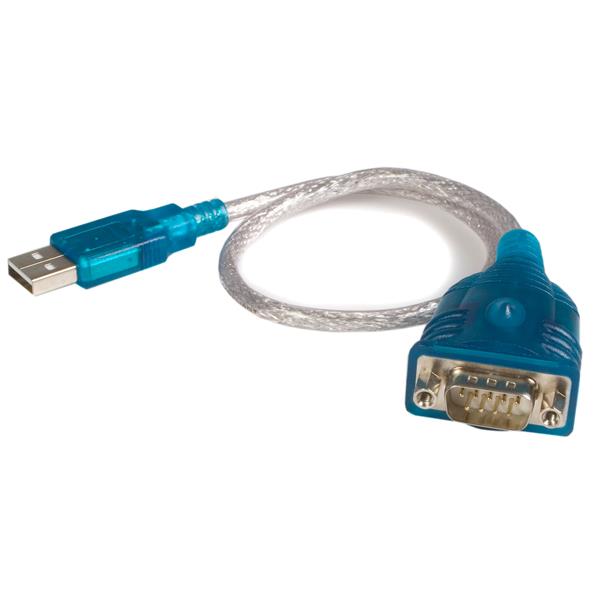
Please don't use this USB TTL RS232 adapter with an Amiga.
- The Amiga's RS232 is real RS232, not TTL, so +-12V. You need a USB RS232 with a proper DE9 port. - The Vcc cable of your TTL RS232 adapter is meant to be used to power a small embedded board. It is a voltage output, not a voltage input. The TTL RS232 adapter is powered by your computer's USB port, so normally the VCC is not connected to anything if your destination device has its own power supply. Definitely don't connect it to +12V on the Amiga, you will fry your TTL adapter and potentially also your USB port. |
|
|
|
30 May 2018, 08:21
|
#44 |
|
Registered User
Join Date: May 2018
Location: Milano
Posts: 59
|
Yes I was just learning about this on the net. If I understand things correctly, then I need an adapter board based on the MAX3232 (or similar) chip. I connect my four TTL pins to this adapter, where the TTL VCC pin is used to route USB power to the adapter board. Then I connect the adapter board via a DB9 to DB25 cable to the Amiga. Correct?
|
|
|
|
30 May 2018, 14:18
|
#45 |
|
Registered User
Join Date: Mar 2015
Location: Karlstad / Sweden
Age: 52
Posts: 1,210
|
you need GND, TX (connected to RX) and RX (Connected to TX) nothing more.
proper serialport is recomended. I have 2 different USB -> RS232 adapters.one works fine. one gives random BSODs (!!) |
|
|
|
30 May 2018, 16:01
|
#46 |
|
-
Join Date: Jul 2003
Location: Helsinki / Finland
Age: 43
Posts: 9,861
|
Yes, it is possible to adapt your current TTL RS232 further to be a 12V RS232 port, but otoh if you're buying more stuff, just get the proper adapter + a 9-25 null modem cable in the first place.
|
|
|
|
30 May 2018, 16:09
|
#47 |
|
Moderator
Join Date: Jan 2002
Location: Chicago, IL
Posts: 3,375
|
Is this a Kickstart backup Util?
|
|
|
|
01 June 2018, 04:00
|
#48 |
|
Registered User
Join Date: May 2018
Location: Beverly HIlls, Ca
Posts: 17
|
OK. I think I've read through all the posts.
I came here looking for a link to a support area, I'm guessing since Chucky is posting here, then this is as good a place to ask a question or two. First, having done a bit of OSS myself, I completely understand the lack of gratitude some folks display for anything you do for free. Thank you, whether it works or not for me, Chucky. I have a dead Amiga 2000 I am trying to diagnose and it's displaying green and black bars on the screen with DIAG ROM. It alternates so, I have tried uploading two images along with this post to attempt to show the animation. To make a long story short, the 2000 originally had a loud POP sound come from it when I turned it on. After much swapping of chips and readings with an Oscilliscope guided by the schematics. I found Paula, Denise, and Agnus dead. (Gary and CIAs appear ok) The 500 went from a black screen with these to a green screen. (Yes.... I know "Chipram" or Agnus, I've read it in a million places. I was hoping to get a bit closer to see if DIAGROM could get me there) The display of DiagROM is odd, so I was hoping someone would know what it meant. Now to the things I read: I assume on a 2000 (rev 4.5) I don't have to do the 3.1 mod like I did with my rev5 A500 to put in a 3.1 chip. I too am using an A520 because my 1084Ses are dead from "storage rot". Looks like I can use a null modem instead, I have a A500 I can use. But, do they not work at all on an NTSC Amiga or is it JUST the display? I can be fat dumb and happy diagnosing over serial if I have to with JRTerm. I'll admit I too bought one (from the guy who sends chucky money, because I like the idea of supporting OSS and love that the seller does that for me). I just figured it was cheaper than buying a ROM and then a programmer. I don't have one, and I really don't need another project standing in my way of repairing my girl. Any help would greatly be appreciated. |
|
|
|
01 June 2018, 04:19
|
#49 | |
|
Registered User
Join Date: Feb 2018
Location: United States
Posts: 81
|
Quote:
With the green screen like yours, you will need to use the serial port and see what the output is. Someone else may have a better diagnosis of your screen though. |
|
|
|
|
01 June 2018, 04:58
|
#50 | |
|
Registered User
Join Date: May 2018
Location: Beverly HIlls, Ca
Posts: 17
|
Quote:
Thanks, chue. Working on that now. I've cobbled together a null modem cable, quite literally with some DB25/9 connectors, a db9 to DB25 converter and some wire. Good news is the 2/3 swap is working and 5 <-> 7 is correct. Trying to get JRComm to play nicely as well from an old disk I converted to adf... if nothing else, I'll find it elsewhere. |
|
|
|
|
01 June 2018, 06:58
|
#51 |
|
Registered User
Join Date: May 2018
Location: Beverly HIlls, Ca
Posts: 17
|
So I gave up on NComm and I have it setup with the null modem to the PC. 9600 N81 and I get giberish on screen.
??BS?@?V?T?(J?*??JR?%R+NPe&:?JRbFNZF2?BFFE?"???? Yes, it looks like the baud rate is wrong, but it's not. I happen to have a Rigol 1054Z and set it up to serial decode the amiga TX and it looks the same when decoded there at 9600 N81. Any ideas? Update: An A500 set to 9600 8N1 sees and sends properly to teh terminal on the PC set to 9600 N81. At least I know the PC terminal software isn't setup incorrectly now. Last edited by crashserious; 01 June 2018 at 08:02. |
|
|
|
01 June 2018, 13:09
|
#52 |
|
Registered User
Join Date: Mar 2015
Location: Karlstad / Sweden
Age: 52
Posts: 1,210
|
ok you get crap on serialport that is one sign of chipmem is borked.
those lines you see. that is 32 of them. it actually shows in light green color bits in chipmem that are correct. and dark green where there is a read error in the memorytest. so I would recomend you to test continuinity test on where bit 10 goes. (d10) as that seems bad. |
|
|
|
01 June 2018, 13:16
|
#53 |
|
Registered User
Join Date: Mar 2015
Location: Karlstad / Sweden
Age: 52
Posts: 1,210
|
(OR bit 7. as in one version (and I cannot remember version) I had that numbering reversed.
 ) )
|
|
|
|
01 June 2018, 13:39
|
#54 | |
|
Banned

Join Date: Sep 2016
Location: UK
Posts: 2,917
|
Quote:
In my experience you can get serial out with no chipram at all... just gives an error very early |
|
|
|
|
01 June 2018, 13:44
|
#55 |
|
Registered User
Join Date: Mar 2015
Location: Karlstad / Sweden
Age: 52
Posts: 1,210
|
Serial out yes. I maybe wrote somewhat.. strange..
however there is some biterrors.. so paula simply doesn't get all data meaning serialoutput will be crap aswell. but the green bars would help you find out what bit is faulty. |
|
|
|
01 June 2018, 17:49
|
#56 | |
|
Registered User
Join Date: May 2018
Location: Beverly HIlls, Ca
Posts: 17
|
o.O
This... makes me very excited. Thank you, Chucky. I was seriously hoping it did something like this! I have 5 chips that should arrive any day now, So I'll be able to swap them out with some educated hunches now instead of just at random. Quote:
|
|
|
|
|
01 June 2018, 18:03
|
#57 |
|
Registered User
Join Date: Mar 2015
Location: Karlstad / Sweden
Age: 52
Posts: 1,210
|
this is most likly not a memorychip. but a trace that is bad.
but IF memory (it can draw thebit all high.. or all low) a easy method figuring out what memorychip it is. is to short the datapins of the memory ICs and look on screen (as it is updated in realtime) and see what chip you can short without 2 stripes gets changed. then you have found the chip. but now I am quite surtain it is a trace or pullup/down resistor. |
|
|
|
03 June 2018, 00:19
|
#58 | |
|
Registered User
Join Date: May 2018
Location: Milano
Posts: 59
|
So I got myself a ttl to rs232 adapter, connected it to my usb-to-ttl cable, fired up minicom, shorted pins 2 and 3, and my usb to rs232 contraption appears to work, as each keypress is echoed back correctly. Then I wired a null modem cable, connecting 2 and 3 on the db25 to 2 and 3 on the db9, and then signal ground from pin 7 on the db25 to pin 5 of the db9. I connect everything, fire up the A500, and ... appears to be not working.
Diagrom recognizes something, because I see serial 9600 bps in the lower left of the screen, but in minicom I only see occasionally a question mark or some sporadic gibberish appearing. No other message from the Amiga appears to reach minicom. So I disconnected the null modem cable, and shorted 2-3, 4-5-6, 8-20-22 on the db25. I have no leds handy, so I just ignored that part. Now if I fire up the a500, and go to serial test of diagrom, it starts to perform the passes but I get negative results on each. The behaviour is different from no loopback connected. Without loopback, each pass is very slow, I assume it moves on after timing out. With loopback, each pass is very quick, but fails: 0 correct received chars, rts2cts bad, rts2dsr bad, dtr2cd bad. I switched the two CIAs, but nothing changed. Can I assume the two rs232 chips are fried? Quote:
|
|
|
|
|
03 June 2018, 02:18
|
#59 |
|
Registered User
Join Date: Mar 2015
Location: Karlstad / Sweden
Age: 52
Posts: 1,210
|
you should not SHORT anything.. you should CROSS so TX on the Amiga is connected to the RX on the PC and the RX on the Amiga is connected to TX on the PC..
if you get an echo. you have shorted and done it wrong as when you send data. it is getting back to the PC again.. and thats wrong and a reason why you do not get any data. |
|
|
|
03 June 2018, 02:19
|
#60 |
|
Registered User
Join Date: Mar 2015
Location: Karlstad / Sweden
Age: 52
Posts: 1,210
|
It is just a standard NULL modem.. usually you need to cross more. but I do not use any handshakes etc. so TX and RX is only used.
|
|
|
| Currently Active Users Viewing This Thread: 1 (0 members and 1 guests) | |
| Thread Tools | |
 Similar Threads
|
||||
| Thread | Thread Starter | Forum | Replies | Last Post |
| DiagROM V0.9 Out | Chucky | support.Hardware | 14 | 31 August 2017 15:35 |
| DiagROM V0.8 | Chucky | support.Hardware | 3 | 27 October 2016 13:49 |
| New "Stable" of my DiagROM | Chucky | support.Hardware | 4 | 07 August 2016 10:28 |
| In search for defective custom ICs to test DiagROM | Chucky | support.Hardware | 2 | 11 May 2015 18:49 |
| Never released??? | tomcat666 | project.aGTW | 18 | 18 January 2010 14:44 |
|
|


