
|
 21 August 2019, 16:44
|
#101 | |
|
Registered User
Join Date: Jan 2004
Location: Yorkshire
Posts: 710
|
How come the oscillator is disabled? I did it the same as Commodore they have the tristate pin connected to ground? or was that a mistake in their schematics?
Yeah the schematics I did aren't pretty but I went for function over appearance, I'm better at laying out.  About the RTC but if you look at the schematics and footprint on the PCB's they expect 20 pins whereas the chips themselves are 18pin and some of the pins are mixed up... although the fact they didn't fix it later suggests you're right. Quote:
Last edited by Mick; 21 August 2019 at 17:00. |
|

|
|
21 August 2019, 17:10
|
#102 |
|
Registered User
Join Date: Jan 2004
Location: Yorkshire
Posts: 710
|
The only problem with "A600 reborn" is it sounds like it's finished lol, I'm not even sure if it will fit inside a case without issues at this point. I'll end up with a pitch fork waving mob after me if someone spends a few hundred quid on PCB's and there's an oversight with dimensions or hole diameters or AmigaPCB was just inaccurate. The whole point of releasing it is so people can build on what I've done and/or fix any mistakes, basically to encourage more development because they don't have to do all of the donkey work and can just be creative instead. I don't have any problem with people using my work if it's for the good of the community and not just personal profit (by selling extortionately priced PCB's).
Last edited by Mick; 21 August 2019 at 17:27. |
|
|
|
21 August 2019, 19:58
|
#103 | |
|
Registered User
Join Date: Mar 2019
Location: UK
Posts: 6
|
Quote:
|
|

|
|
21 August 2019, 20:05
|
#104 |
|
Registered User
Join Date: Jan 2004
Location: Yorkshire
Posts: 710
|
i didn't know that I just figured the extra copper inside would give the connector more strength, if it's confirmed I'll fix it. I'm sort of learning on the job.
|
|
|
|
21 August 2019, 20:45
|
#105 | |
|
Registered User
Join Date: Sep 2006
Location: Thunder Bay, Canada
Posts: 4,323
|
Quote:
for 5 boards, 4 layer the cost would be ~$100 CAD total and then add shipping and custom fees, (10 boards would be ~$140 totaal). 2 layer would be ~$45 CAD total for 5 board edit; price is based on bard size ~ 330mm x 200mm Last edited by kipper2k; 21 August 2019 at 20:53. |
|
|
|
|
21 August 2019, 23:19
|
#106 | |
|
Registered User
Join Date: Jan 2008
Location: United Kingdom
Age: 46
Posts: 733
|
Quote:
The memory expansion connector needs hasrd gold fingers for reliability, this pushes the cost up. 5 PCB with ENIG finish, shipped to UK + VAT + handling fees ~£106 10 PCB with ENIG gfinish, shipped to UK + VAT + handling fees ~£142 5 standard PCBs, shipped to UK + VAT + handling fees ~£95 10 standard PCBs, shipped to UK + VAT + handling fees ~£128 @Mick How about 'A600 revived' for this PCB design and the reborn for the tweaked one? Keep the power planes 2mm from the bevelled edge of the expansion connector, that should leave enough room. For a reborn design, I'd drop the RAM exmpansion slot and add the extra 1MB chip and provision 4/8MB FAST RAM in the space. 4 SRAM chips would work nicely
|
|
|
|
|
22 August 2019, 01:06
|
#107 |
|
Registered User
Join Date: Jan 2004
Location: Yorkshire
Posts: 710
|
I just see what I'm doing as a sort of springboard for others who know more to tweak/improve upon what I've done and I'll update my version as I learn more myself. I don't know about name I thought Open A600 was alright because it's self explanatory.
I think it needs a disclaimer for now saying that it's not been tested and to use files at their own risk and maybe point people here to share any feedback or issues they've found/fixed so others can follow? I'd hoped it might become a sort of community project where people will be like "hey I did a version of the board with xxxxx here's the files if anyone likes it or I'll sell you a PCB for cost of PCB and postage". That sort of thing. The person who replaces the keyboard controller will probably have the most popular board lol. Last edited by Mick; 22 August 2019 at 01:18. |
|
|
|
22 August 2019, 08:55
|
#108 |
|
Registered User
Join Date: Jan 2004
Location: Yorkshire
Posts: 710
|
I've updated the files the ground plane now stops short of where the expansion connector pins start so they don't even overlap now.
Thanks for pointing it out xyzzy1, one step closer to perfection. 
|
|
|
|
22 August 2019, 19:23
|
#109 |
|
Registered User
Join Date: Jan 2004
Location: Yorkshire
Posts: 710
|
 
|
|
|
|
22 August 2019, 22:35
|
#110 |
|
Registered User
Join Date: Jan 2008
Location: United Kingdom
Age: 46
Posts: 733
|
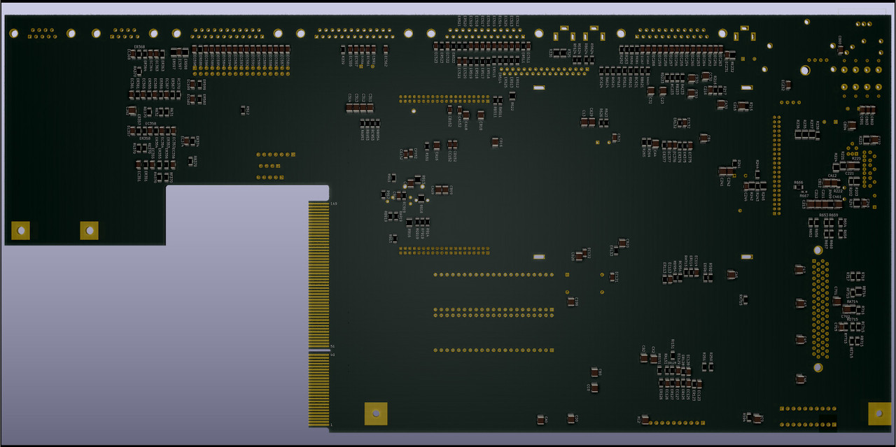
The PCB outline fits nicely inside the case.
MT6 needs to move slightly, maybe 1.5mm to the left and 1.5mm down, see the second photo. Not sure about this, the CAD data matches my measurements but not the case. Ooops.  I'm getting there with the edits to remove the U12/U13 power net mess, it takes a bit of time. Will then check the layout/tracking. |
|
|
|
22 August 2019, 22:49
|
#111 |
|
Registered User
Join Date: Jan 2004
Location: Yorkshire
Posts: 710
|
That's a good idea I didn't think of that.
It looks like 9 pin ports could do with moving down a bit as well? I think the external ports need to fairly precise to fit inside the metal shielding don't they? if I could get a board with some of the through hole stuff desoldered I could have it all exact within about an hour. I'm concerned about hole diameters of some of the custom footprints as well as positions of external connectors. I'll move MT6 and re-uplaod in a sec. edit: I found another issue in the schematics while doing A1200, R224 needed connecting to R225, new files uploaded. Last edited by Mick; 24 August 2019 at 16:25. |
|
|
|
25 August 2019, 21:07
|
#112 |
|
Registered User
Join Date: Jan 2004
Location: Yorkshire
Posts: 710
|
Well that rounds off an exciting couple of months, I'll have to find a new purpose in life now.
   If I use a power plane instead of routing power manually would I need to move decoupling caps closer to IC's? |
|
|
|
27 August 2019, 11:45
|
#113 | |
|
ex. demoscener "Bigmama"
Join Date: Jun 2012
Location: Fyn / Denmark
Posts: 1,624
|
Quote:
The cap is for making up for inductance in your power/ground traces, so if you have power and ground planes connected directly to through-hole IC's, I'd say a cap would have little to no effect. |
|
|
|
|
27 August 2019, 12:29
|
#114 |
|
Registered User
Join Date: Jan 2004
Location: Yorkshire
Posts: 710
|
Alright thanks. It's just I read that they also act as a stored charge for in case of dips in voltage and I thought that with having a plane location might be a bit more important as you could have other nearby IC's also taking power from them. Then again they're only small decoupling capacitors so are probably only for smoothing? I think I'm probably showing my lack of electrical knowledge and over thinking here.
I'm a bit stuck on what I can do with the A600 without a board to measure, if anyone has a faulty board that they wouldn't mind lending me (preferably not the shorter 2B though) I could probably get into position to be confident enough to order a PCB. |
|
|
|
27 August 2019, 13:54
|
#115 |
|
Registered User
Join Date: Mar 2015
Location: Bristol/UK
Posts: 166
|
Might be a good idea to have a new thread for the A1200 to avoid confusion between the two.
|
|
|
|
11 September 2019, 14:24
|
#116 |
|
Registered User
Join Date: Sep 2019
Location: Voorthuizen
Posts: 4
|
Hi Mick,
Just reading this whole thread, very inpresive what you created sofar! If not already provide, I can donate you a600 board, a rev 1.3 Or 1.5. |
|
|
|
12 September 2019, 10:18
|
#117 |
|
Registered User
Join Date: Jan 2004
Location: Yorkshire
Posts: 710
|
Hi Justme14, thanks for the offer but I'm unsure what to do to be honest. I sent the files to someone I know within the community yesterday who has already released some VERY good things and who I know will make a brilliant job of finishing it, he says he will finish it but he is busy working for a few weeks and I don't want to put any pressure on him. I sent him the A1200 files as well. As an incentive I told him if wants to make a bit of money out of it to help fund his own development then I wouldn't mind. If he doesn't do it I could have a go at finishing it myself but he has a lot more knowledge/experience in this area.
|
|
|
|
16 September 2019, 09:27
|
#118 |
|
Registered User
Join Date: Sep 2019
Location: Voorthuizen
Posts: 4
|
Hi Mick, I can understand,sounds like a good way to go.
|
|
|
|
20 September 2019, 11:48
|
#119 |
|
Registered User
Join Date: Jan 2004
Location: Yorkshire
Posts: 710
|
If you want to send me a board I could fix the dimensions and I might try to get some boards made but if I did I would need someone to build one and potentially fault find? do you have the metal shield as well? I'd probably prefer the rev 1.5.
Stedy when you said the oscillator was connected to ground which would disable it did you mean those two extra capacitors on the main oscillation output that are in the schematics but not present on real boards? |
|
|
|
20 September 2019, 13:29
|
#120 |
|
Tech Guru
Join Date: Dec 2015
Location: Oxnard, CA
Posts: 189
|
Is this ready to have boards made and test build? I am willing to have a couple made and sacrifice one of my 600 boards to build one here if you are? Cool project!
|
|
|
| Currently Active Users Viewing This Thread: 1 (0 members and 1 guests) | |
| Thread Tools | |
 Similar Threads
|
||||
| Thread | Thread Starter | Forum | Replies | Last Post |
| Legal: Amiga schematics | michaelz | support.Other | 25 | 15 March 2017 13:13 |
| First Amiga 600 FPGA Accelerator - Vampire 600 | majsta | Hardware mods | 736 | 18 July 2016 18:31 |
| aminet Clean schematics Amiga Classics | cosmicfrog | support.Hardware | 14 | 12 March 2016 20:03 |
| Amiga 2000 keyboard schematics | Brannigan | support.Hardware | 11 | 10 February 2014 08:24 |
| What if DCE donated Amiga Hardware Schematics? | Yoto | Retrogaming General Discussion | 47 | 15 May 2012 15:04 |
|
|


