 |
|
|
#1 |
|
Registered User
Join Date: Apr 2008
Location: Tauranga/New Zealand
Posts: 202
|
Auto Mouse/Joystick switcher - Help!
Hey all,
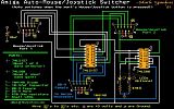
I found a link to a file on Aminet called mswitch.lha, which contained some docs and a schematic for building your own Auto mouse/joystick switcher. Now, I'm fairly comfortable using a soldering iron and messing about with electronics, (to a point!), but I'm finding this diagram a bit confusing:  If anyone has actually built one of these, any chance of a more step-by-step guide? As another option, has anyone built a manual mouse/joystick switcher, and if so, do you have any instructions/guides etc? Any help would be appreciated! 
|
|
|
|
|
#2 |
|
Registered User
Join Date: Aug 2004
Location: www.amigakit.com
Posts: 2,015
|
We have our new Automatic Mouse/Joystick switchers now available here:
http://amigakit.leamancomputing.com/...roducts_id=961 |
|
|
|
|
#3 |
|
Registered User
Join Date: Apr 2008
Location: Tauranga/New Zealand
Posts: 202
|
hehehe, that was fast! Thanks for that - I still may look at that option, as they're a very reasonable price, but this is the "Hardware Mods" thread, and sometimes half the fun is trying to build something yourself...

|
|
|
|
|
#4 |
|
Precious & fragile things
Join Date: Feb 2009
Location: Victoria, Australia
Posts: 1,946
|
What aspect do you find confusing?
|
|
|
|
|
#5 |
|
Registered User
Join Date: Apr 2008
Location: Tauranga/New Zealand
Posts: 202
|
Well, I can see where most things go in the diagram, and what should be soldered to what etc, but what about all the +5v and ground connections - I 'm not sure what to do with those - do you solder them so all +5v connect together, same with ground etc? Also, top left of diagram it shows a capacitor with ground one side and +5v the other, but I don't get whwre this is, as the parts list shows only 1 capacitor of this type, but where in the circuit does it go?
I guess if someone has done this, and could just "expand" the instructions a bit, that'd be awesome. If they've got some pics, even better! Otherwise, like I said, I'd be happy with a "manual" switch option too if someone has some schematics/instructions... 
|
|
|
|
|
#6 |
|
Registered User
Join Date: Aug 2004
Location: www.amigakit.com
Posts: 2,015
|
We can supply it in pieces if you wish ;-)
|
|
|
|
|
#7 |
|
uber cool demi god
Join Date: Jun 2006
Location: Kent/England
Posts: 2,073
|
|
|
|
|
|
#8 |
|
Registered User
Join Date: Apr 2008
Location: Tauranga/New Zealand
Posts: 202
|
|
|
|
|
|
#9 | |
|
Precious & fragile things
Join Date: Feb 2009
Location: Victoria, Australia
Posts: 1,946
|
Quote:
http://www.noahjames.com/C-D/ELECTRON/LESPAUL.JPG a common ground is represented by the green line, if that helps? @Matthew or FOL, Your answer was gold, made me laugh plenty! |
|
|
|
| Currently Active Users Viewing This Thread: 1 (0 members and 1 guests) | |
| Thread Tools | |
 Similar Threads
|
||||
| Thread | Thread Starter | Forum | Replies | Last Post |
| Regarding auto joy/mouse switcher | VoltureX | support.Hardware | 0 | 12 January 2012 15:26 |
| D.I.Y Auto Video Switcher for B/C Vision PPC and Indivision AGA | phipscube | Hardware mods | 1 | 01 March 2011 13:10 |
| Auto Monitor Switcher (A1200) | Zetr0 | Hardware mods | 1 | 04 April 2010 02:38 |
| Mouse/joystick switcher needed | CFou! | support.Hardware | 8 | 04 June 2006 13:37 |
| DIY auto mouse/joystick switch | brian | support.Hardware | 13 | 01 May 2004 02:55 |
|
|