
|
 11 February 2010, 03:18
|
#81 | |
|
FPGAmiga rulez!
Join Date: Dec 2007
Location: South of France
Age: 50
Posts: 155
|
Quote:
This it what I do also. I personnaly do not use the EPCS chips they are too expensive. Actually, they are ST/Numonyx chips with a different marking. The Spansion chips work too. Get a 16Mbit part (just $2), that will give you plenty of room for storing software after the serial configuration (extra Kickstart, autoboot ROM  ). ).Regards, Frederic |
|

|
|
11 February 2010, 07:56
|
#82 | |
|
Registered User
Join Date: Feb 2008
Location: Saint-Petersburg / Russia
Posts: 324
|
Quote:
Not sure what are the overshoots and undershoots, could you please tell more? |
|
|
|
|
11 February 2010, 07:59
|
#83 | |
|
Registered User
Join Date: Feb 2008
Location: Saint-Petersburg / Russia
Posts: 324
|
Quote:
Would be nice if they have the same pinout as EPCS. |
|
|
|
|
11 February 2010, 14:59
|
#84 | |
|
FPGAmiga rulez!
Join Date: Dec 2007
Location: South of France
Age: 50
Posts: 155
|
Quote:
Two footprints are available (not counting the QFN) : SOIC-8 and SOIC-16. The SOIC-8 footprint fits inside the SOIC-16 footprint by rotating it 90 degree. This is what I do on my layout so I can support any flash size from 1Mbit to 128Mbit. What is important to look at are the flash commands and especially the format of the flash identification command. This is what Quartus checks first when you program a flash with the .JIC file. For example, the Atmel and SST flashes are not compatible with Quartus but if you design your own flash loader, you can use them. Regards, Frederic |
|
|
|
|
11 February 2010, 15:16
|
#85 | |
|
FPGAmiga rulez!
Join Date: Dec 2007
Location: South of France
Age: 50
Posts: 155
|
Quote:
They are due to wrong impedance matching that creates reflections on the propagation lines. The serie resistor is here to match the impedance. It has to be located close to the source on a unidirectional line (i.e address) and in the middle on a bidirectional line (i.e. data). On short distance, they are most of the time not necessary and can create more problems. At least, I put always a resistor on the clock lines, usually 22 ohms. If you have drive current settings on the pins of your Cyclone II, by reducing the current, you decrease the slew rate and the risk of overshoot and undershoot. You can check that with a high speed oscilloscope but keep in mind that the 20pF of a standard oscilloscope probe changes the characteristics of your line. You need a FET probe. You can also make an adapter using one of you quickswitch which is certainly FET based. Hope it helps. Regards, Frederic |
|
|
|
|
12 February 2010, 01:42
|
#86 |
|
Registered User
Join Date: Aug 2001
Location: Connecticut USA
Posts: 617
|
Slew rate of signal determines the "frequency" of the signal (... using the good old sine wave formula, Voltage=Amplitude*sin(2*pi*frequency*time).
You take the derivative of the above formula, with respect to time: dVoltage/dTime = A*2*pi*F*cos(2*pi*F*T) Then, the frequency is where the change is greatest, i.e. where cos(xxxx...) is 1, and get dV/dT=A*2*pi*F. Substitute in your slew rate for dV/dT, your signal amplitude, and solve for frequency. Take the reciprocal of the frequency to get your period, then take 1/4 of your period. This is your "transmission line" cutoff time. Multiply the cutoff time by the speed that electricity travels in the copper medium, to get the "transmission line" cutoff distance. If the length of the trace from your driver to your receiver is more than the cutoff distance, your trace acts like a transmission line, and you will get over/undershoot, and possibly ringing. I've seen 40% overshoot on my board, and just today I say a 75% overshoot on an RS422 (4V signal, shooting up to 7V) driver line. |
|
|
|
12 February 2010, 10:27
|
#87 | ||
|
Registered User
Join Date: Feb 2008
Location: Saint-Petersburg / Russia
Posts: 324
|
Quote:
Here's what Cyclone II datasheet says on series termination: ----------------------------- I/O Driver Impedance Matching (RS) and Series Termination (RS) Cyclone II devices support driver impedance matching to the impedance of the transmission line, typically 25 or 50 Ω. When used with the output drivers, on-chip termination (OCT) sets the output driver impedance to 25 or 50 Ω by choosing the driver strength. Once matching impedance is selected, driver current can not be changed. Table 10–7 provides a list of output standards that support impedance matching. All I/O banks and I/O pins support impedance matching and series termination. Dedicated configuration pins and JTAG pins do not support impedance matching or series termination. Table 10–7. Selectable I/O Drivers with Impedance Matching and Series Termination I/O Standard === Target RS (Ω) 3.3-V LVTTL/CMOS === 25 ----------------------------- So I guess I can use these on-chip termination resistors just to be on the safe side. Also, limited Current Strength Setting is available for LVTTL/LVCMOS, can be turned on also. Quote:
|
||
|
|
|
13 February 2010, 08:58
|
#88 |
|
Registered User
Join Date: Feb 2008
Location: Saint-Petersburg / Russia
Posts: 324
|
Cyclone II manual says on-chip termination (OCT) is available on all I/O banks. However, I cannot activate it for all pins. Some can be OCT'd, some can not. This can be either me or Quartus II software, or both. So if I fail to resolve the termination issue, I will let it as it is, hoping the thing will survive.
(Oh, and the EPCS1 turned out to be too small to accomodate both firmware and SFL loader. Gotta get a bigger one next week). Last edited by tnt23; 15 February 2010 at 08:39. |
|
|
|
13 February 2010, 16:59
|
#89 | |
|
FPGAmiga rulez!
Join Date: Dec 2007
Location: South of France
Age: 50
Posts: 155
|
Quote:
The compatible SPI brands seems to be ST/Numonyx, EON Silicon Solutions, Spansion and Macronix. So far, I used Spansion and ST without any issue. Regards, Frederic |
|
|
|
|
13 February 2010, 19:59
|
#90 | ||
|
Registered User
Join Date: Feb 2008
Location: Saint-Petersburg / Russia
Posts: 324
|
Quote:
Quote:
|
||
|
|
|
13 February 2010, 20:59
|
#91 | |
|
FPGAmiga rulez!
Join Date: Dec 2007
Location: South of France
Age: 50
Posts: 155
|
Quote:
Macronix 16Mb : MX25L1605D-M2 ST/Numonyx 16Mb : M25P16-VMW Eon 16Mb : EN25F16-100H AMIC 16Mb : A25L016M-F Spansion 16Mb : S25FL016A0LMFI01 Today, it is hard to get something under 16Mb. Even 16Mb is getting phased out by Spansion. Regards, Frederic |
|
|
|
|
14 February 2010, 16:51
|
#92 |
|
Registered User
Join Date: Feb 2008
Location: Saint-Petersburg / Russia
Posts: 324
|
Indeed, turning the compression option on allowed to program the EPCS1.
Soldered the Quickswitches in place, put the board in A4000. Did not observe any magic smoke. The Amiga boots OK, but the board is not seen in the system. Obviously my Autoconfig code is not working. 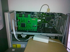
|
|
|
|
14 February 2010, 18:18
|
#93 | |
|
FPGAmiga rulez!
Join Date: Dec 2007
Location: South of France
Age: 50
Posts: 155
|
Quote:
Anyway, it is time to use Signaltap  . Now, you have at least a Zorro III logic analyzer . . Now, you have at least a Zorro III logic analyzer .What kind of JTAG interface are you using ? It looks bigger than a USB Blaster. Is it a homemade clone  ? ?Regards, Frederic |
|
|
|
|
14 February 2010, 19:29
|
#94 | |
|
Registered User
Join Date: Feb 2008
Location: Saint-Petersburg / Russia
Posts: 324
|
Quote:
I don't use the CONFIG_DONE pin, I believe the FPGA is configured OK as I also can access the EPCS through the SPL megafunction. Going to introduce myself to Signaltap  My Rigol digital scope has a built-in cheap logic analyzer (8/16 TTL channels) which is going to be very handy. My Rigol digital scope has a built-in cheap logic analyzer (8/16 TTL channels) which is going to be very handy.I will also pass the Zorro signals like /CONFIGn, /CFGOUTn, /FCS and /SLAVEn through to the debug I/O pins for some live performance. A serial output can also be implemented to help debugging. Right, the grey box at the front is homemade USB blaster clone I borrowed from another friend
Last edited by tnt23; 14 February 2010 at 19:37. |
|
|
|
|
15 February 2010, 18:20
|
#95 |
|
Registered User
Join Date: Feb 2008
Location: Saint-Petersburg / Russia
Posts: 324
|
FrenchShark, your Signaltap hint was very helpful. Spent a day fiddling with it, and guess what
The Autoconfig now works more or less! Still no memory on the board, it is configured as an I/O PIC, but at least we know full cycles work for Autoconfig. |
|
|
|
16 February 2010, 01:12
|
#96 | |
|
Registered User
Join Date: Aug 2008
Location: London / Canada
Posts: 781
|
Quote:

|
|
|
|
|
16 February 2010, 01:46
|
#97 |
|
Brosol
Join Date: Jan 2010
Location: Vancouver, BC, Canada
Posts: 85
|
Wow Indeed! I'm hoping for an alternative to rare & insanely high priced cards like DKB 3128 for my A3000D.
Last edited by Brosol; 16 February 2010 at 18:51. |
|
|
|
16 February 2010, 10:34
|
#98 |
|
Coder/webmaster/gamer
Join Date: Oct 2001
Location: Canberra/Australia
Posts: 2,630
|
And of course the Zorro ]I[ spec is in the RKRM Hardware Manual. Sorry if anyone has already pointed this out.
|
|
|
|
16 February 2010, 14:39
|
#99 | |
|
Registered User
Join Date: Feb 2008
Location: Saint-Petersburg / Russia
Posts: 324
|
Quote:
The AmigaHardRefManual.pdf from The Zone covers Autoconfig only for Zorro II. Do you happen to have a link to latest RKRM somewhere?
|
|
|
|
|
16 February 2010, 14:51
|
#100 |
|
Thalion Webshrine
Join Date: Jan 2004
Location: Oxford
Posts: 14,337
|
|
|
|
| Currently Active Users Viewing This Thread: 1 (0 members and 1 guests) | |
| Thread Tools | |
 Similar Threads
|
||||
| Thread | Thread Starter | Forum | Replies | Last Post |
| Amiga 3000 Zorro Bus Problems | Ze_ro | support.Hardware | 18 | 30 April 2021 06:27 |
| Wanted - A4000 Tower case and Zorro bus board | AmigaFun | MarketPlace | 8 | 03 June 2011 13:03 |
| Zorro Bus Termination... | chiark | support.Hardware | 3 | 15 October 2010 09:50 |
| PCMCIA card reader in Zorro bus | protek | Hardware mods | 17 | 06 November 2009 00:46 |
| Zorro II Card - Zorro III Slot ? | THX1138 | support.Hardware | 4 | 03 May 2003 11:03 |
|
|


