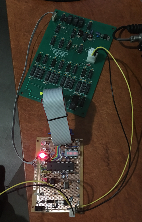
I got the thing working tonight

The error output from the CD32 CD drive is being simulated by the same microcontroller
that’s also reading the parallel port input back from the error counter PCB.
One of the control pins on the parallel port that would have been controlled by the test station computer
enables counting, and the other is probably the counter reset.
So far I’m just letting the counter overflow, and it begins from zero again.
The LED bargraph displays the eight bit output of the parallel port (from the counter PCB),
and the 4x 10mm LEDs indicate the simulated 4 bit CD drive error output
that would normally come from Sony CDX2500BQ CD drive interface chip (currently from the test PCB).
The real power connector for the board I got as a free sample from TE Connectivity

Video of testing:
[ Show youtube player ]